Design method of blade suction surface groove for controlling flow separation
A suction surface and blade technology, applied to blade support components, mechanical equipment, engine components, etc., to reduce weight, reduce fuel consumption, and improve the characteristics of large angle of attack
- Summary
- Abstract
- Description
- Claims
- Application Information
AI Technical Summary
Problems solved by technology
Method used
Image

Examples
Embodiment 1
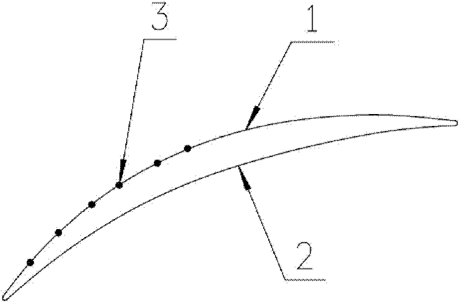
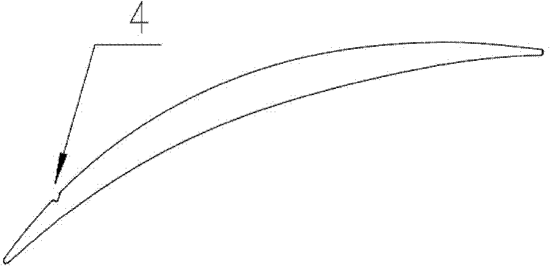
[0026] In this embodiment, a certain cascade primitive blade type (as shown in the appendix) Figure 5 shown) is a design object. The design inlet Mach number of this primitive airfoil is 0.7, and the critical angle of attack is 8°. To design the groove 4 on the blade suction surface 1 of the original primitive airfoil, it is first necessary to determine the initial position of the groove starting point, the initial projection length of the groove on the blade suction surface profile, and the initial description of the groove curve. functional equation.
[0027] To determine the initial position of the groove starting point, it is necessary to calculate and analyze the flow field of the original element blade cascade channel. The initial position of the groove starting point is selected within the projection range of the separation zone development stage on the blade suction surface, and the projection range of the separation zone development stage on the blade suction surfa...
Embodiment 2
[0038] In this embodiment, a certain cascade primitive blade shape is taken as the design object. The design inlet Mach number of the primitive airfoil is 0.5, and the critical angle of attack is 8°. To design the groove on the blade suction surface of the original primitive airfoil shape, it is first necessary to determine the initial position of the groove starting point, the initial projection length of the groove on the blade suction surface shape line, and the initial function equation describing the groove curve .
[0039] To determine the initial position of the starting point of the groove, it is necessary to calculate and analyze the flow field of the original primitive blade type cascade channel. The initial position of the starting point of the groove is selected within the projection range of the development stage of the separation zone on the suction surface of the blade, and the projection range of the development stage of the separation zone on the suction surf...
Embodiment 3
[0050] In this embodiment, a certain cascade primitive blade shape is taken as the design object. The design inlet Mach number of the basic airfoil is 0.6, and the critical angle of attack is 7°. To design the groove on the blade suction surface of the original primitive airfoil shape, it is first necessary to determine the initial position of the groove starting point, the initial projection length of the groove on the blade suction surface shape line, and the initial function equation describing the groove curve .
[0051] To determine the initial position of the starting point of the groove, it is necessary to calculate and analyze the flow field of the original primitive blade type cascade channel. The initial position of the starting point of the groove is selected within the projection range of the development stage of the separation zone on the suction surface of the blade, and the projection range of the development stage of the separation zone on the suction surface ...
PUM
 Abstract
Description
Claims
Application Information
 - R&D
- Intellectual Property
- Life Sciences
- Materials
- Tech Scout
- Unparalleled Data Quality
- Higher Quality Content
- 60% Fewer Hallucinations
Browse by: Latest US Patents, China's latest patents, Technical Efficacy Thesaurus, Application Domain, Technology Topic, Popular Technical Reports.
© 2025 PatSnap. All rights reserved.Legal|Privacy policy|Modern Slavery Act Transparency Statement|Sitemap|About US| Contact US: help@patsnap.com