
Selective non-catalytic reduction denitration system of circulating fluidized bed boiler

A circulating fluidized bed, selective technology, applied in the field of flue gas denitrification, can solve the problems of affecting the injection effect of reducing agent, the effect of denitrification is not obvious, and the wear of reducing agent nozzle, so as to be suitable for large-scale promotion, beneficial to industrial application, Facilitates a fully proceeding effect

Inactive Publication Date: 2012-07-18
TSINGHUA UNIV +1
View PDF5 Cites 4 Cited by
  • Summary
  • Abstract
  • Description
  • Claims
  • Application Information

AI Technical Summary

Problems solved by technology

When the injection position is at the inlet, such as US Patent No. 5462718 and 11 / 747010, the reducing agent nozzle is at an angle of 90° to the cyclone separator inlet. Since the flue gas at this position contains a large number of particles, it is easy to cause the reducing agent nozzle to wear and nozzle clogging affect the effect of reducing agent injection
When the injection position is at the outlet, such as U.S. Patent 6325985, because the cyclone separator has the best reaction conditions for SNCR reaction, this type of design does not use the method of injecting the reducing agent into the separator, and the denitrification effect is not obvious

Method used


Image

  • Selective non-catalytic reduction denitration system of circulating fluidized bed boiler
  • Selective non-catalytic reduction denitration system of circulating fluidized bed boiler
  • Selective non-catalytic reduction denitration system of circulating fluidized bed boiler

Examples


Embodiment Construction

[0015] The principle, structure and implementation of the present invention will be further described below in conjunction with the accompanying drawings.

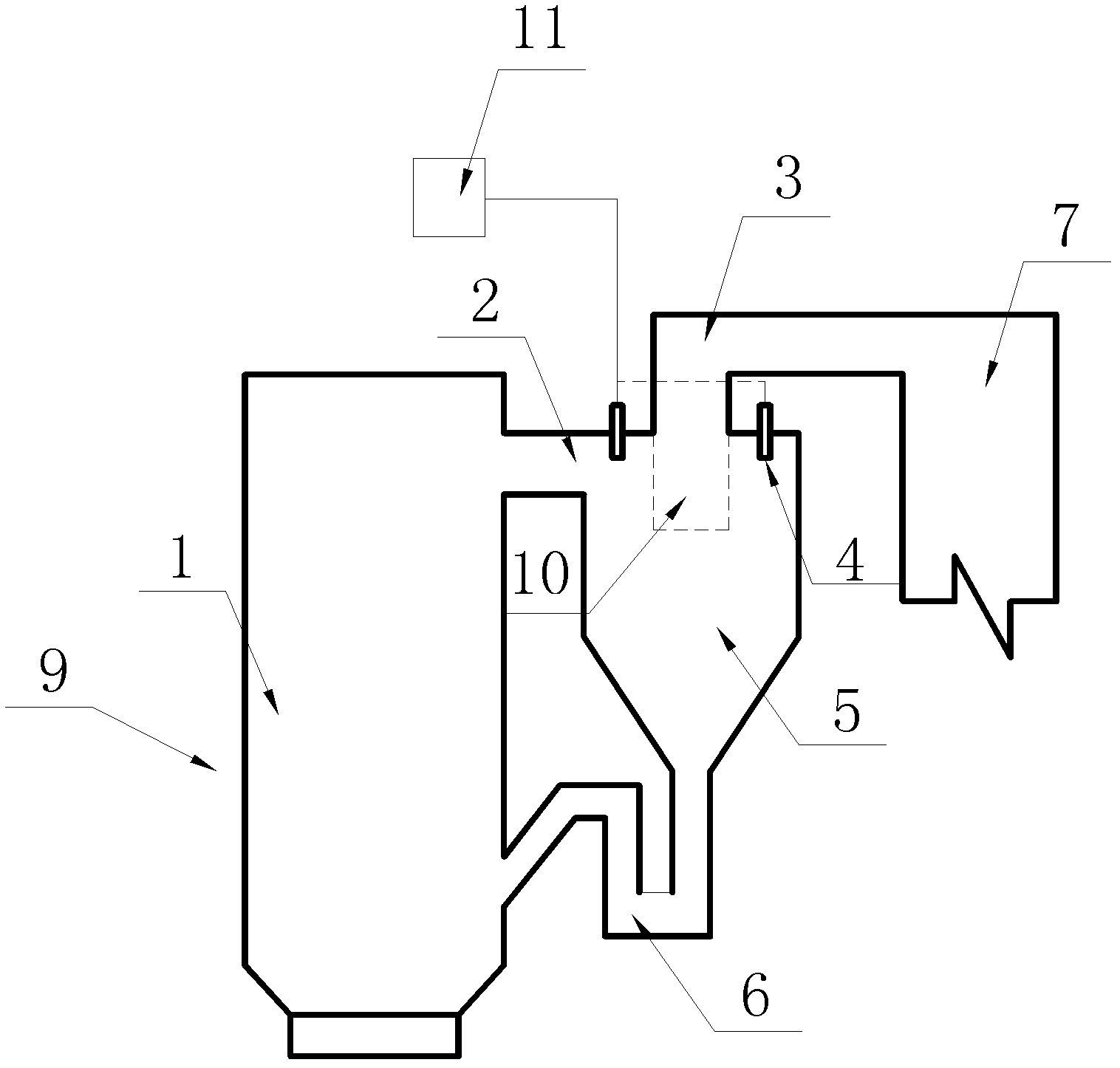
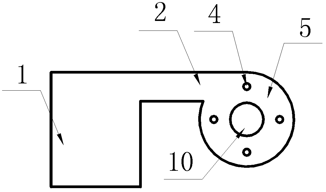
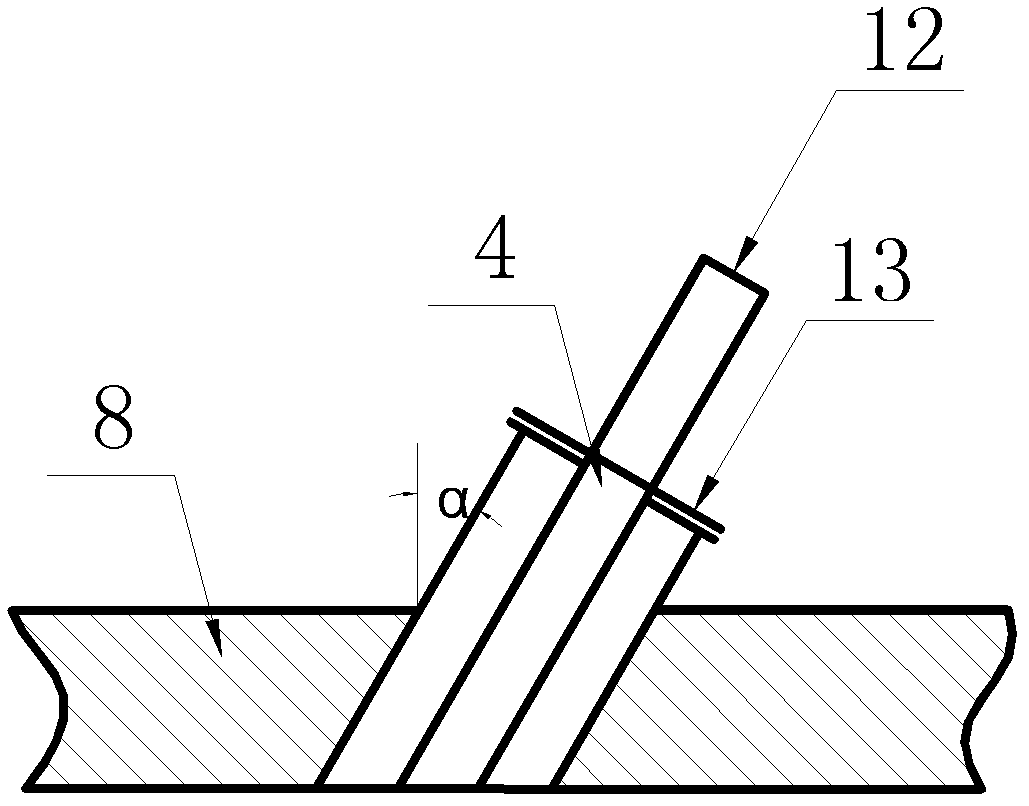
[0016] figure 1 It is a schematic diagram of the overall structure of a selective non-catalytic reduction denitrification system for a circulating fluidized bed boiler. Including furnace 1, reducing agent and atomizing air proportioning conveying system 11, cyclone separator 5, return system 6 and tail flue 7, in order to achieve sufficient mixing of reducing agent and flue gas and improve the degree of SNCR reaction, in the A plurality of atomizing nozzles 4 are evenly arranged on the top plate 8 of the separator on the outer periphery of the cyclone separator core cylinder 10, and the atomizing nozzles 4 are connected to the reducing agent proportioning delivery system 11 through pipelines. figure 2 and image 3 They are respectively the arrangement form of the atomizing nozzle 4 and the specific structure of the nozz...


PUM


Abstract

The invention discloses a selective non-catalytic reduction denitration system of a circulating fluidized bed boiler, belonging to the technology of flue gas denitration. The system comprises a hearth, a reducing agent and atomization air proportion conveying system, a cyclone separator, a material return system and a tail flue, and is characterized in that: multiple atomization nozzles are uniformly arranged on the upper top plate of the separator on the periphery of a core cylinder of the cyclone separator; the openings of the atomization nozzles face downwards; and an angle of 0-60 degrees is formed between the reducing agent spraying direction and the vertical direction. According to the invention, by adopting reasonable spraying position and angle and nozzle number for the selective non-catalytic reducing agent, the mixing degree of the reducing agent and NOx in flue gas is increased, the denitration reaction is promoted, the efficiency and feasibility of the selective non-catalytic reduction denitration are improved, the leakage of the reducing agent is reduced, and the industrial application of the selective non-catalytic reduction denitration method is facilitated.

Description

technical field [0001] The invention relates to a selective non-catalytic reduction (SNCR) denitrification system applied to a circulating fluidized bed boiler, belonging to flue gas denitrification technology. Background technique [0002] Nitrogen oxides (NOx) are the three major pollutants emitted by coal-fired power plants (SO 2 , one of NOx and total suspended particulate matter (TSP). With the increasingly stringent national and local environmental protection policies, flue gas denitrification technology has received more and more attention. [0003] Currently, the commonly used flue gas denitrification technologies include selective catalytic reduction (SCR) and selective non-catalytic reduction (SNCR). Selective Catalytic Reduction (SCR) is the use of reducing agents (ammonia, urea, etc.) to reduce NOx to N under the action of a catalyst 2 Technology. SCR has the advantages of high efficiency and low leakage rate, but it also has obvious disadvantages, such as hi...

Claims


Application Information

Patent Timeline
Patent Type & Authority Applications(China)
IPC IPC(8): B01D50/00
Inventor 李穹吴玉新沈解忠吕俊复张海
Owner TSINGHUA UNIV
Learn More