Valve with safety protrusion

A protruding part and outlet end technology, applied in the field of new aerosol valves, can solve the problems of not proposing to obtain rights, not disclosing valves, etc.

Inactive Publication Date: 2012-07-11
艾尔塔彻姆控股公司 +1
View PDF12 Cites 11 Cited by
  • Summary
  • Abstract
  • Description
  • Claims
  • Application Information

AI Technical Summary

Problems solved by technology

[0013] Furthermore, a valve is provided for dispensing a container of pressurized fluid which is moisture resistant and thus will inhibit water diffusion and / or absorption which would cause sticking and clogging of the valve
[0014] The prior art does not disclose a valve according to the invention, nor do these documents suggest the presently acquired rights associated therewith

Method used


Image

  • Valve with safety protrusion
  • Valve with safety protrusion
  • Valve with safety protrusion

Examples


Embodiment Construction

[0021] Description of the preferred embodiment

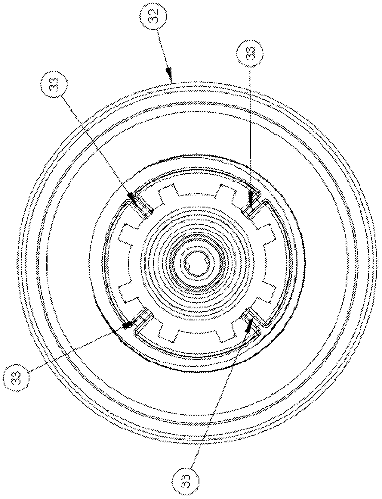
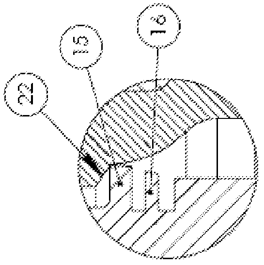
[0022] refer to figure 1 and 2 And according to the invention, a valve (1) for dispensing a container of pressurized fluid is proposed, the valve (1) comprising a grommet (2) and a stem (6), the grommet (2) having a plug system (10) and Delimiting a channel (3) having an inlet end (4) and an outlet end (5), a rod (6) is slidably disposed in the channel (3), a grommet (2) comprising a A first part (7) and a second part (8) arranged at the inlet end (4), characterized in that the first part (7) has a protrusion ( 11).

[0023] The valve (1) is designed to be placed in the opening of the container dome (9) for controlling the dispensing of fluid from said container. According to a preferred embodiment, the valve (1) is designed to be riveted in the opening of the container dome (9). A radially outwardly extending plug system (10) is provided and will rivet the valve against the edge (30) of the container dome (9). The radiall...


PUM


Abstract

The present invention is directed to a valve (1) for a container comprising a grommet 5 (2) having a plug system (10) and defining a channel (3) with an inlet end (4) and an outlet end (5) and a stem (6) slideably arranged in the channel (3), whereby the grommet (2) comprises at least two parts (7) and (8) sealingly engaged, said first part (7) having protrusion within said second part (8).

Description

field of invention [0001] The present invention relates to novel aerosol valves for pressurized fluid containers, more particularly for one-component polyurethane foam applications. Background of the invention [0002] The storage of fluids under pressure in containers (tanks or vessels) is known in a wide range of applications. Fluid is typically dispensed from the container by means of a valve provided in the cup of the container. [0003] Well known applications are sprayable foams used in industrial applications and by hobbyists. As such, containers with sprayable foam can be exposed to quite extreme conditions in terms of temperature and pressure. [0004] In these extreme cases, the pressure in the container may increase and the valve may separate from the container, creating a potential safety issue. [0005] In order to prevent the above problems, various safety measures are adopted, such as providing an overpressure relief valve or providing a "burst part" in the...

Claims


Application Information

Patent Timeline
Patent Type & Authority Applications(China)
IPC IPC(8): B65D83/14
CPCB65D83/756B65D83/202B65D83/48B65D83/46B65D83/20
Inventor 阿斯特·德施瑞瓦凯茜·德玛尔特拉尔乔迪·德梅迪特马尔·摩宁
Owner 艾尔塔彻姆控股公司
Why Eureka
Try Eureka