
Processing device

A treatment device and mixing tank technology, applied in mixers with rotating stirring devices, transportation and packaging, chemical/physical processes, etc., can solve problems such as complex structure, high device price, flow control of refractory materials, etc., and achieve simple Effects that handle conditions, are easy to control, and are simple in structure

Active Publication Date: 2012-07-11
NIPPON COKE & ENG
View PDF5 Cites 5 Cited by
  • Summary
  • Abstract
  • Description
  • Claims
  • Application Information

AI Technical Summary

Problems solved by technology

[0008] However, since the processing device 210 has a complex structure, the device is expensive
In addition, there are also problems in that it is difficult to control the flow of the treated matter due to the complicated structure, and it is difficult to find the optimum treatment conditions

Method used


Image

  • Processing device
  • Processing device
  • Processing device

Examples


Embodiment

[0084] Figure 8 is a photomicrograph of a product processed by the processing device 10 . The treatment is a mixture of cross-linked PMMA (70%) and titanium dioxide (30%) with an average particle size of about 5 μm; Figure 9 It is a photomicrograph of a product processed by a conventional processing device that does not have a collision plate, and the processed objects are the same. By comparing the two, the effect of the collision plate is clearly shown. That is, in Figure 8 In , all the particles are spherical and its surface is processed relatively smooth. Unlike this, in Figure 9 In , the shape of the particle is not necessarily spherical and its surface remains in a rough state.


PUM


Abstract

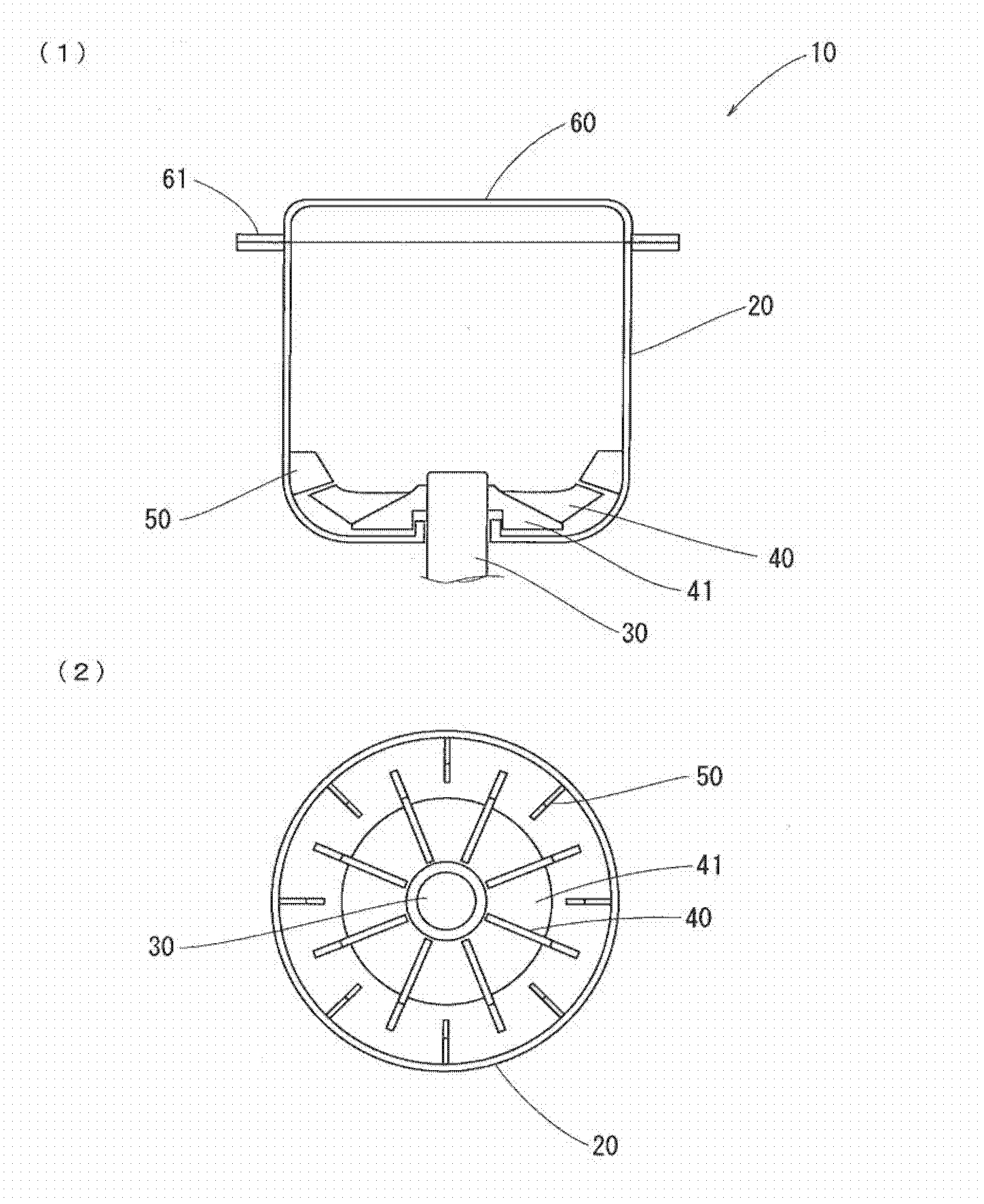
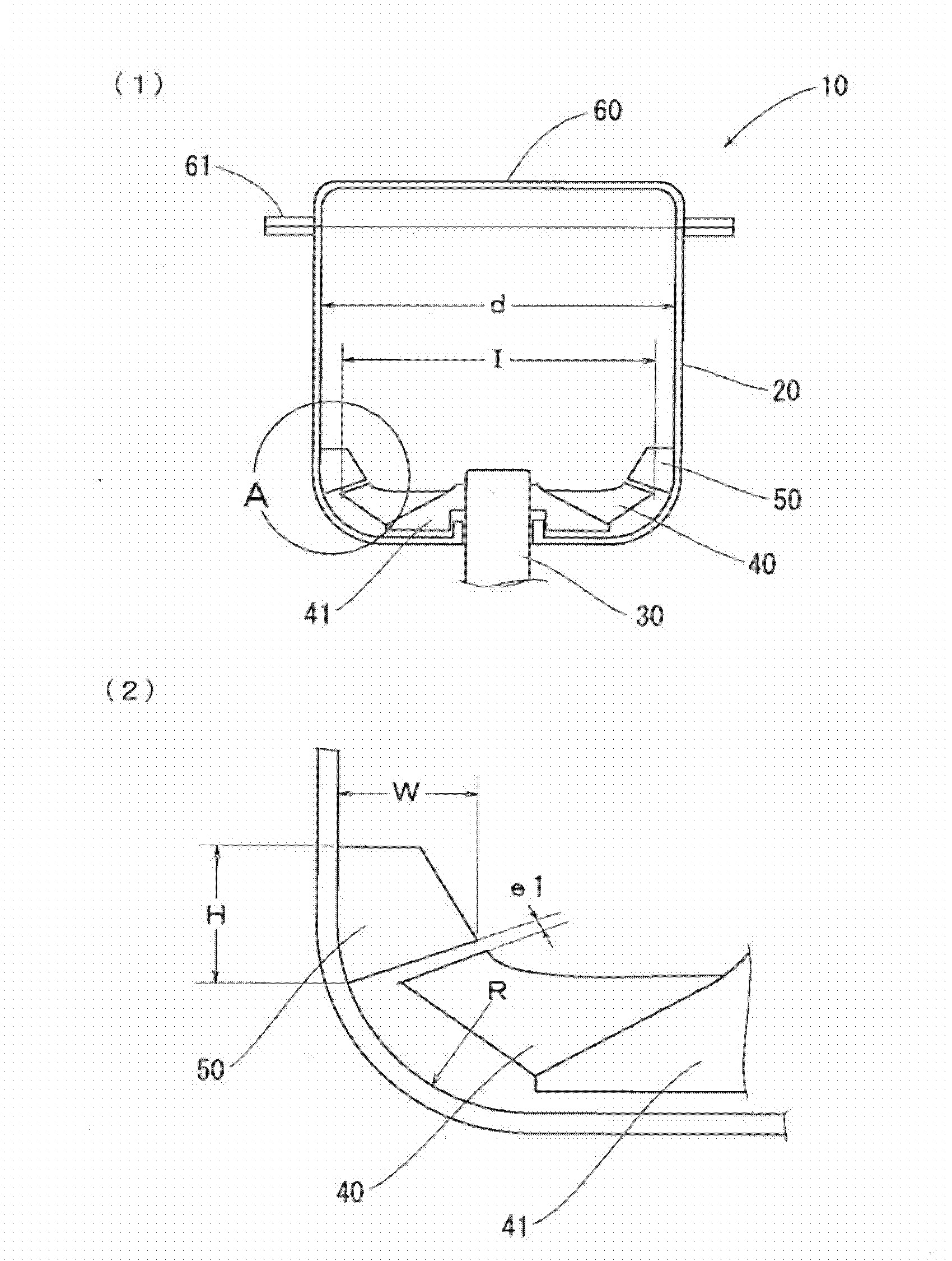
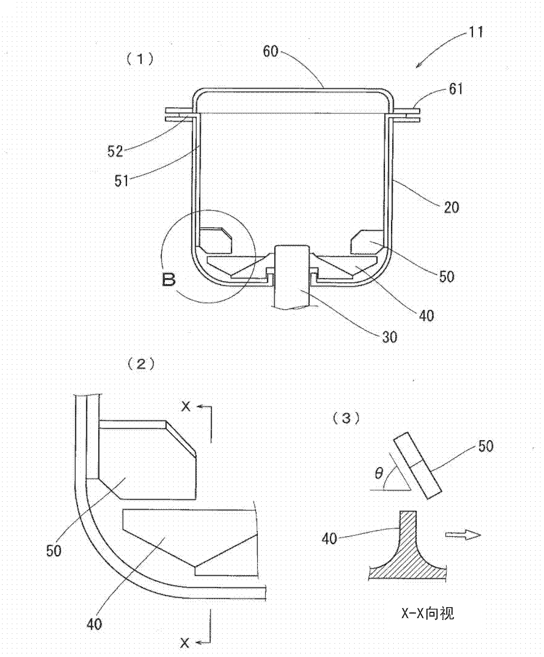
Disclosed is a processing device that performs processes such as compositing by applying strong pressure or shear force to granular materials. Said processing device, which has a simple structure and can easily find optimal processing conditions, is provided with: a vertical mixing vessel (20); a rotating shaft (30) inserted through the bottom of the mixing vessel (20); a plurality of stirring blades (40) provided on the rotating shaft (30); and a plurality of impact plates (50) affixed to the mixing vessel (20). Letting the diameter of the mixing vessel (20) be d, the minimum distance between the stirring blades (40) and the impact plates (50) is at most 0.1d.

Description

technical field [0001] The present invention relates to a processing device for processing powder and granular bodies, in particular to a processing device capable of advanced processing such as compounding or spheroidizing. Background technique [0002] When treating powders and granules with a particle size of micron precision level or nanometer level, the following treatment is generally adopted for the powder granules, that is, the particles with a larger aspect ratio are spheroidized, or the particle size is spheroidized. Smaller particles are coated on the surface of larger particles, or multiple particles are combined into integrated spherical particles. [0003] For example, in Patent Document 1, it is described as Figure 10 The processing device shown. This processing device 110 has: a horizontal cylindrical mixing tank 120 ; a rotating shaft 130 provided through one side wall; and a plurality of stirring blades 140 provided on the rotating shaft 130 . Since the ...

Claims


Application Information

Patent Timeline
Patent Type & Authority Applications(China)
IPC IPC(8): B01J2/10B01F7/16B01J2/00
CPCB01F7/186B01F7/00275B01J2/10B01F3/18B01F7/162B01F23/60B01F27/1123B01F27/9021B01F27/808B01J19/18B01F27/80
Inventor 中野要介小矢岛良章石川修关根靖由高桥雄介
Owner NIPPON COKE & ENG
Learn More