
Voltage comparator

A technology of voltage comparator and current source, applied in the direction of instruments, electrical components, adjusting electrical variables, etc. low consumption effect

Inactive Publication Date: 2012-07-11
CSMC TECH FAB1 +1
View PDF3 Cites 10 Cited by
  • Summary
  • Abstract
  • Description
  • Claims
  • Application Information

AI Technical Summary

Problems solved by technology

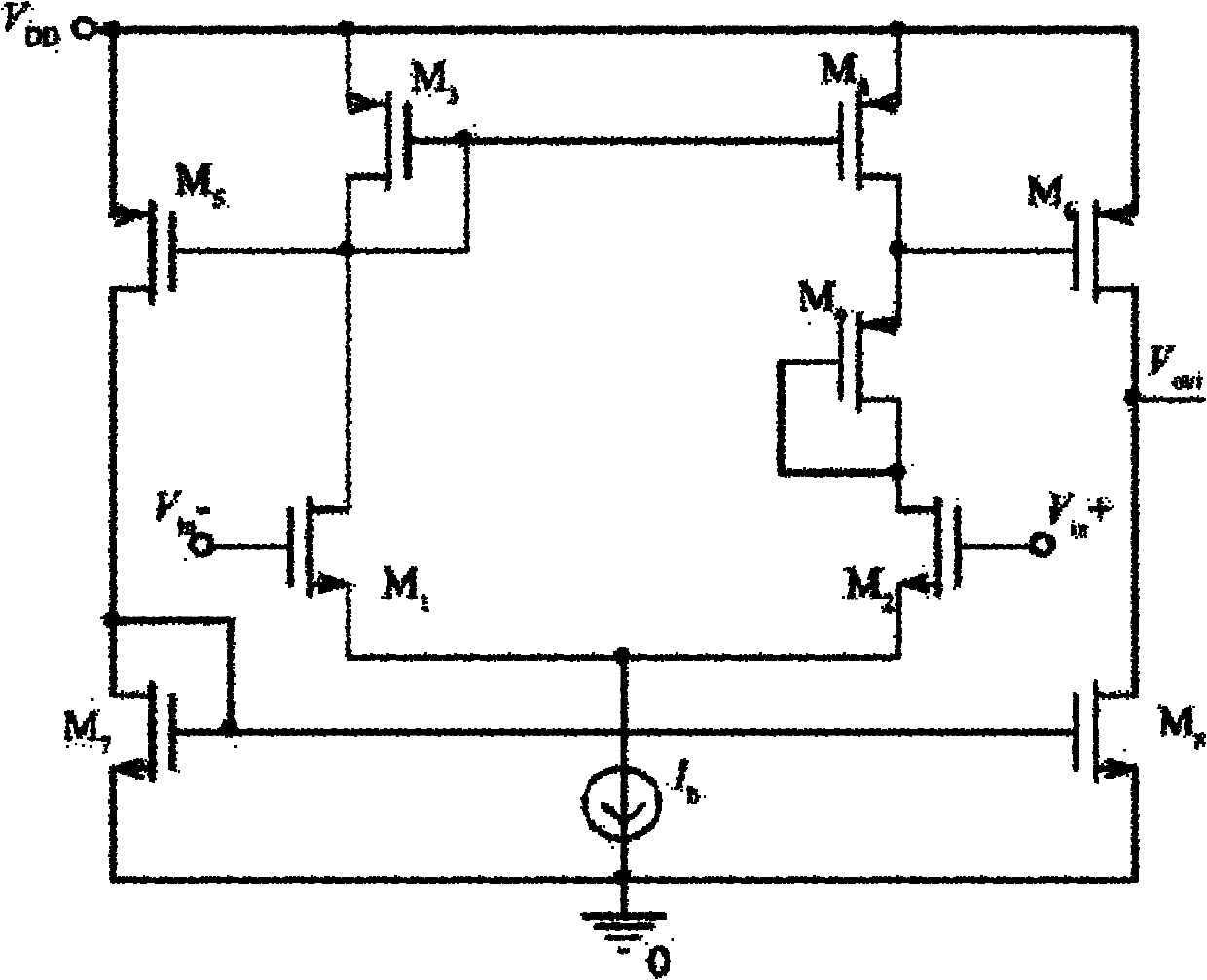
[0009] The problem however is that, figure 1 Although the topology of the voltage comparator shown in can obtain better anti-noise performance, but its delay is too long, it will produce a large error
In addition, the power consumption of the voltage comparator is relatively large, and if you try to reduce its power consumption, it will cause a further increase in delay

Method used


Image

  • Voltage comparator
  • Voltage comparator
  • Voltage comparator

Examples


Embodiment Construction

[0038] In order to make the above objects, features and advantages of the present invention more comprehensible, specific implementations of the present invention will be described in detail below in conjunction with the accompanying drawings.

[0039] In the following description, a lot of specific details are set forth in order to fully understand the present invention, but the present invention can also be implemented in other ways different from those described here, and those skilled in the art can do it without departing from the meaning of the present invention. By analogy, the present invention is therefore not limited to the specific examples disclosed below.

[0040] Secondly, the present invention is described in detail in combination with schematic diagrams. When describing the embodiments of the present invention in detail, for the convenience of explanation, the cross-sectional view showing the device structure will not be partially enlarged according to the gener...


PUM


Abstract

The invention provides a voltage comparator, which comprises a current source, a differential gain module and a conversion module, wherein the current magnitude of the current source is of nanoampere level; the differential gain module comprises a first transistor, a second transistor, a third transistor and a fourth transistor; the first transistor and the second transistor are connected with the current source respectively; the third transistor and the fourth transistor form a current mirror structure; the third transistor is connected with the first transistor; and the fourth transistor is connected with the second transistor through a ninth transistor for forming asymmetric differential gain. According to the voltage comparator provided by the invention, since the transistor which works in a sub-threshold region has higher transconductance-to-current ratio Gm / Ib than the transistor which works in a saturation region, the power consumption is lower; and in order to reduce the power consumption, the bias current in the voltage comparator provided by the embodiment is low, and the time delay of the voltage comparator is also low.

Description

technical field [0001] The invention relates to image sensor technology, in particular to a voltage comparator. Background technique [0002] With the rapid development of VLSI technology, CMOS image sensors have functions such as integration in a single chip, A / D conversion, signal processing, automatic gain control, precision amplification and storage, which greatly reduces system complexity and reduces cost, thus showing a strong momentum of development. In addition, it also has outstanding advantages such as low power consumption, single power supply, low operating voltage (3V ~ 5V), high yield, and random access to local pixels. Therefore, CMOS image sensors have developed extremely rapidly and have been widely used in different fields such as consumer digital products, X-ray detection, astronomical observation, and medical detection. [0003] The voltage comparator is the key circuit structure in the CMOS image sensor, and its performance in terms of delay, power con...

Claims


Application Information

Patent Timeline
Patent Type & Authority Applications(China)
IPC IPC(8): H03K5/24G05F1/56
CPCH03K5/2481H03K5/2472
Inventor 程亮
Owner CSMC TECH FAB1
Learn More