Direct-current power supply hot plug slow starting control circuit and control method
A technology of slow-start circuit and DC power supply, which is applied in the direction of electrical components and output power conversion devices, etc. It can solve the problems of converter output power failure, discrete component characteristic parameter drift, MOS tube avalanche breakdown, etc., and achieve simple circuit, It is convenient for economical selection and avoids the effect of avalanche breakdown
- Summary
- Abstract
- Description
- Claims
- Application Information
AI Technical Summary
Problems solved by technology
Method used
Image
Examples
Embodiment 1
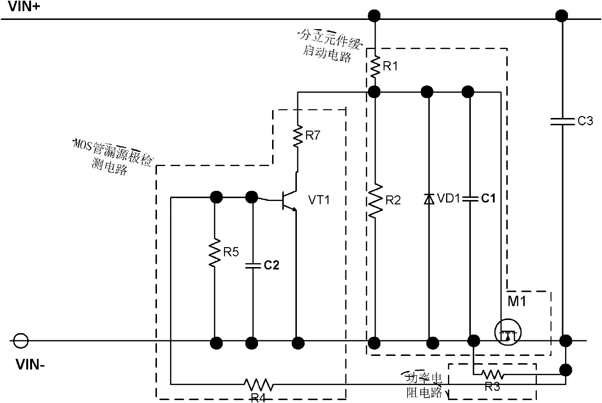
[0038] Such as image 3As shown, the DC power supply slow-start control circuit of the present invention includes a discrete element slow-start circuit, a power resistor circuit, and a MOS tube drain-source detection circuit. in:
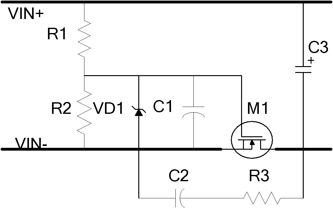
[0039] The discrete component slow start circuit includes MOS tube M1, resistors R1, R2, capacitor C1, and voltage regulator diode VD1; wherein, R1, R2 form a voltage divider circuit, which is connected in series between the positive and negative input terminals of the power supply, and VD1 and C1 are connected in parallel Between the connection point of R1 and R2 and the negative input terminal of the power supply, the gate of the MOS transistor M1 is connected to the connection point of the resistors R1 and R2, and the source is connected to the negative input terminal of the power supply.
[0040] The power resistor circuit includes a resistor R3 connected between the source and the drain of the MOS transistor M1; it may also include multiple re...
Embodiment 2
[0047] Such as Figure 4 As shown, the DC power supply slow-start control circuit of the present invention includes a discrete element slow-start circuit, a power resistor circuit, and a MOS tube drain-source detection circuit.
[0048] The discrete component slow start circuit is made up of MOS tube M1, resistors R1, R2, capacitor C1, voltage regulator diode VD1; the power resistor circuit is made up of resistor R3; the MOS tube drain-source detection circuit is made up of resistors R4, R5 , R7, triode VT1, and capacitor C2. The resistors R4 and R5 are connected in series and R3 in parallel to form a voltage divider circuit. The base of the triode VT1 is connected to the connection point between R4 and R5, and the emitter is connected to the other end of R5. One end, the collector is connected to the resistor R7, and the other end of the resistor R7 is connected to the junction of R1 and R2.
[0049] In this embodiment, the DC power supply slow start control circuit further ...
Embodiment 3
[0056] Such as Figure 5 As shown, the DC power supply slow-start control circuit of the present invention includes a discrete element slow-start circuit, a power resistor circuit, and a MOS tube drain-source detection circuit.
[0057] The discrete component slow start circuit is made up of MOS tube M1, resistors R1, R2, capacitor C1, voltage regulator diode VD1; the power resistor circuit is made up of resistor R3; the MOS tube drain-source detection circuit is made up of resistors R4, R5 , R7, triode VT1, and capacitor C2, the resistors R4 and R5 are connected in series to form a voltage divider circuit, the triode VT1 and R5 are connected in parallel, the base is connected to the connection point between R4 and R5, and the emitter is connected to R5 another side.
[0058] In this embodiment, the DC power supply slow start control circuit further includes an enable control circuit.
[0059] One implementation of the enabling control circuit is as follows: the enabling con...
PUM
 Abstract
Description
Claims
Application Information
 - R&D
- Intellectual Property
- Life Sciences
- Materials
- Tech Scout
- Unparalleled Data Quality
- Higher Quality Content
- 60% Fewer Hallucinations
Browse by: Latest US Patents, China's latest patents, Technical Efficacy Thesaurus, Application Domain, Technology Topic, Popular Technical Reports.
© 2025 PatSnap. All rights reserved.Legal|Privacy policy|Modern Slavery Act Transparency Statement|Sitemap|About US| Contact US: help@patsnap.com


