Thermoelectric module and manufacture method thereof

A technology of a thermoelectric module and a manufacturing method, which is applied in the manufacture/processing of thermoelectric devices, thermoelectric device parts, thermoelectric devices using only Peltier or Seebeck effect, etc. Sudden reduction in module service life, reliability and other issues

Inactive Publication Date: 2012-07-11
IND TECH RES INST
View PDF6 Cites 5 Cited by
  • Summary
  • Abstract
  • Description
  • Claims
  • Application Information

AI Technical Summary

Problems solved by technology

[0007] However, when making assembly figure 1 When the thermoelectric module 100 is used, the thickness 126 of the solder alloy layer 120 is not easy to adjust and control, and when the thermoelectric module is used, the solder alloy layer 120 may melt and be fixed because the hot end of the thermoelectric module is overheated. The clamp pressure of the thermoelectric module 100 is extruded, and the interface thickness 126 gradually decreases, thereby causing the thermoelectric materials 142 and 144 to fall and crack. cause thermoelectric module short circuit, etc.
The above-mentioned problems all lead to the reliability problem of a sudden decrease in the service life of the thermoelectric module

Method used


Image

  • Thermoelectric module and manufacture method thereof
  • Thermoelectric module and manufacture method thereof
  • Thermoelectric module and manufacture method thereof

Examples


no. 1 example

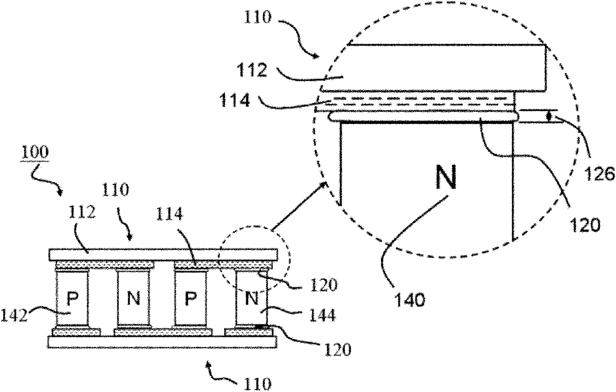
[0072] figure 2 A schematic diagram of a thermoelectric module according to a first embodiment of the present invention is shown. The thermoelectric module 200 includes a first substrate 211 and a second substrate 212 oppositely arranged, a plurality of P-type thermoelectric materials 242 and N-type thermoelectric materials 244, a plurality of first metal electrodes 214 and a second metal electrode 216, a plurality of first A solder alloy layer 221 and a second solder alloy layer 222, and supports. In this embodiment, strip supports 284 are used as supports.

[0073] Multiple pairs of thermoelectric materials 240 are disposed between the first substrate 211 and the second substrate 212, each pair of thermoelectric materials 240 includes a P-type thermoelectric material 242 and an N-type thermoelectric material 244 electrically connected, and each pair of thermoelectric materials N-type The thermoelectric material 244 is electrically connected to the P-type thermoelectric ma...

no. 2 example

[0091] Figure 4 A schematic diagram of a thermoelectric module according to a second embodiment of the present invention is shown. Different from the thermoelectric module 200 of the first embodiment, the thermoelectric module 300 of the second embodiment uses a granular support 384 as a support. Furthermore, in the thermoelectric module 300 , the cross-arranged multi-nodal P-type thermoelectric materials 342 and multi-nodal N-type thermoelectric materials 344 are formed by bonding P1 and P2, N1 and N2 thermoelectric materials, respectively.

[0092] Figure 4 Among them, the thermoelectric module 300 includes a first substrate 311 and a second substrate 312 oppositely arranged, a plurality of nodal P-type thermoelectric materials 342 and nodal N-type thermoelectric materials 344, a plurality of first metal electrodes 314 and second metal electrodes 314 An electrode 316 , a plurality of first and second solder alloy layers 321 , 322 , and a particulate support 384 .

[009...


PUM

PropertyMeasurementUnit
Heightaaaaaaaaaa
Particle sizeaaaaaaaaaa

Abstract

The invention discloses a thermoelectric module and a manufacture method of the thermoelectric module. The thermoelectric module comprises a first base plate, a second base plate, a plurality of P type thermoelectric materials, a plurality of N type thermoelectric materials, first metal electrodes, second metal electrodes, first welding alloy layers, second welding alloy layers and a support object, wherein the thermoelectric materials are arranged between the first base plate and the second base plate and each pair of thermoelectric materials comprises a P type thermoelectric material and an N type thermoelectric material which are electrically connected through the first metal electrode (positioned between the first base plate and the lower end surface of the thermoelectric materials), and the N type thermoelectric material is then electrically connected with the other adjacent P type thermoelectric material through the second metal electrode (positioned between the second base plate and the upper end surface of the thermoelectric materials). The first welding alloy layers are connected with the first metal electrodes and the lower end surfaces of the P / N type thermoelectric materials, and the second welding alloy layers are connected with the second metal electrodes and the upper end surfaces of the P / N type thermoelectric materials. The support object is positioned in a position of at least one of the first welding alloy layers and the second welding alloy layers, and in addition, the melting point is higher than the liquid phase line temperature of the first welding alloy layers and the second welding alloy layers.

Description

technical field [0001] The invention relates to a thermoelectric module and a manufacturing method thereof, in particular to a generating thermoelectric module capable of stable operation at high temperature and a manufacturing method thereof. Background technique [0002] Thermoelectric modules, by switching the direction of the current input to the thermoelectric module, can increase or decrease the temperature of the end surface of the thermoelectric module, and have been mass-produced and used in precise temperature control units. In addition, through the temperature difference ΔT between the hot end temperature (Th) and the cold end temperature (Tc) of the two ends of the thermoelectric module, the thermoelectric module can also convert the temperature difference between the two ends of the thermoelectric module into electrical energy output, thus recovering environmental heat. The conversion efficiency η of a thermoelectric power generation device is mainly determined ...

Claims


Application Information

Patent Timeline
IPC IPC(8): H01L35/08H01L35/32H01L35/34
Inventor 范元昌陈俊沐朱旭山王正全黄振东
Owner IND TECH RES INST
Why Eureka
Try Eureka