Bistable liquid crystal grating

A bistable liquid crystal and grating technology, applied in optics, nonlinear optics, static indicators, etc., can solve the problem of insufficient energy saving, and achieve the effect of energy saving and adjustable electric field

Inactive Publication Date: 2012-07-11
SHANTOU UNIV
View PDF4 Cites 14 Cited by
  • Summary
  • Abstract
  • Description
  • Claims
  • Application Information

AI Technical Summary

Problems solved by technology

[0004] At present, in the existing technology, most of the liquid crystal gratings use nematic liquid crystals, which must work under a continuous electric field, and there are deficiencies in energy saving.

Method used


Image

  • Bistable liquid crystal grating
  • Bistable liquid crystal grating
  • Bistable liquid crystal grating

Examples


Embodiment Construction

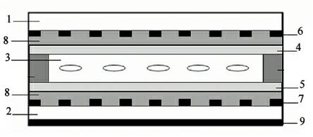
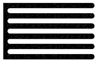
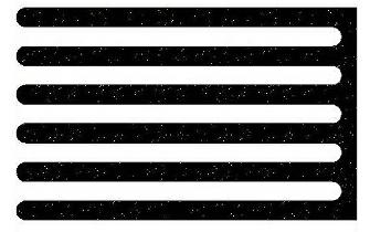
[0020] refer to figure 1 and Figure 5 , the present invention is a bistable liquid crystal grating, comprising an upper glass substrate 1 and a lower glass substrate 2, and a liquid crystal layer 3, the two glass substrates are soda-lime glass, and the upper and lower glass substrates 1 and 2 are provided with combs A transparent electrode layer and an alignment layer. The lower glass substrate 2 is provided with a light absorbing layer 9. The alignment layer is divided into an upper alignment layer 4 and a lower alignment layer 5. The upper alignment layer 4 and the lower alignment layer 5 are rubbed alignment layers. A barrier layer 8 is provided between the upper and lower glass substrates 1, 2 and the upper and lower alignment layers 4, 5 respectively, the barrier layer 8 is silicon dioxide, and the liquid crystal layer 3 is arranged between the two glass substrates 1, 2, The liquid crystal poured into the liquid crystal layer 3 is cholesteric liquid crystal, the liquid ...


PUM


Abstract

The invention relates to a liquid crystal grating which comprises upper and lower glass base plates and a liquid crystal layer, wherein a comb-shaped transparent electrode layer and an orienting layer are arranged on both of the glass base plates; the orienting layer is divided into an upper orienting layer and a lower orienting layer; a barrier layer is arranged between each glass base plate and the orienting layer; the liquid crystal layer is arranged between the two glass base plates and are in direct contact with the orienting layers; a conductive layer is divided into an upper conductive electrode and a lower conductive electrode; and both the upper conductive electrode and the lower conductive electrode are round comb-shaped electrodes and are oppositely arranged. Generally, a nematic phase liquid crystal is applied to a common liquid crystal grating; the liquid crystal filled into the liquid crystal grating is cholesteric liquid crystal; according to the bistable characteristics of the cholesteric liquid crystal, the liquid crystal grating subjected to a certain surface treatment is capable of working in a null field state; different voltage pulses are utilized to realize the adjustable electric field for controlling the diffraction strength of the liquid crystal grating; the liquid crystal grating provided by the invention is simple in manufacturing process, is energy-saving and is free from polarization film; and the diffraction strength of the grating can be controlled by adjusting the electric field.

Description

technical field [0001] The invention relates to an optical element—a grating, in particular to a liquid crystal grating. Background technique [0002] Gratings, also known as diffraction gratings, are optical components that use the principle of multi-slit diffraction to disperse light. A grating is a flat glass or metal sheet engraved with a large number of parallel equal-width and equidistant slits. The number of slits is large, usually ranging from tens to thousands per millimeter. The diffraction of monochromatic parallel light through each slit of the grating and the interference between each slit form a pattern with wide dark fringes and thin bright fringes. These sharp, thin and bright fringes are called spectral lines. The position of the spectral line varies with the wavelength. When the polychromatic light passes through the grating, the spectral lines of different wavelengths appear at different positions to form a spectrum. The spectrum formed by light passing ...

Claims


Application Information

Patent Timeline
IPC IPC(8): G02F1/133G02F1/1343
Inventor 黄翀聂传岗欧阳艳东
Owner SHANTOU UNIV
Why Eureka
Try Eureka