
State detection device for high-potential thyristor

A state detection device and thyristor technology, applied in the direction of single semiconductor device testing, etc., can solve the problems of complicated power supply circuit and achieve the effect of reliable operation

Inactive Publication Date: 2012-07-11
ZHUZHOU NAT ENG RES CENT OF CONVERTERS
View PDF8 Cites 10 Cited by
  • Summary
  • Abstract
  • Description
  • Claims
  • Application Information

AI Technical Summary

Problems solved by technology

The power supply of the detection circuit is obtained from the high potential thyristor, and the power supply circuit is more complicated
The original method of detecting the on-off state of the optocoupler phototransistor is limited by the voltage isolation capability of the optocoupler, and is no longer applicable when the thyristor potential is higher than a certain value.

Method used


Image

  • State detection device for high-potential thyristor
  • State detection device for high-potential thyristor
  • State detection device for high-potential thyristor

Examples


Embodiment Construction

[0023] The following will clearly and completely describe the technical solutions in the embodiments of the present invention with reference to the drawings in the embodiments of the present invention. Apparently, the described embodiments are only some of the embodiments of the present invention, not all of them. Based on the embodiments of the present invention, all other embodiments obtained by persons of ordinary skill in the art without making creative efforts belong to the protection scope of the present invention.

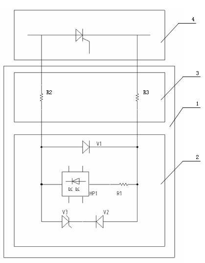
[0024] as attached image 3 As shown, a specific embodiment of a high-potential thyristor state detection device of the present invention that is specifically applied to high-potential system thyristor state detection in high-voltage and high-power power electronic devices is given. The present invention will be further described below in conjunction with the accompanying drawings and specific embodiments.

[0025] A specific implementation mode is applied ...


PUM


Abstract

The invention discloses a state detection device for a high-potential thyristor. The device comprises a detection circuit board and a detection resistor circuit, wherein the detection circuit board is connected with the detection resistor circuit and connected with a detected thyristor through the detection resistor circuit; the detection resistor circuit comprises detection resistors; the detection circuit board comprises two parallel branches, a first parallel branch comprises a first diode, and a second parallel branch comprises an optical fiber transmitter; when the detected thyristor withstands a forward voltage, current flows through the first diode in the detection circuit board to protect the optical fiber transmitter from withstanding over-high backward voltage; and when the detected thyristor withstands the backward voltage, the current flows through the optical fiber transmitter, the optical fiber transmitter transmits a signal through an optical fiber, and withstanding of the backward voltage by the detected thyristor is detected. The state detection device for the high-potential thyristor is applicable to a high-potential system, a special power circuit is not required to be provided for the detection circuit board, the state of the thyristor can be easily detected, and the optical fiber transmitter can reliably operate in the high-potential system.

Description

technical field [0001] The invention relates to a thyristor detection circuit, in particular to a simple and convenient thyristor state detection device suitable for high-potential systems in high-voltage and high-power power electronic devices using thyristors. Background technique [0002] In high-voltage and high-power power electronic devices with thyristors, it is often necessary to detect whether the thyristors have broken down. Whether the thyristor has the ability to withstand a certain reverse voltage is the basis for judging whether it breaks down. On this basis, the traditional detection method is to connect several resistors in parallel at both ends of the thyristor to be detected, and determine whether the thyristor is subjected to reverse voltage by detecting the voltage of one of the resistors; Detect the on-off state of the phototransistor of the optocoupler to determine whether the thyristor is subjected to reverse voltage. Among the existing technologies,...

Claims


Application Information

Patent Timeline
IPC IPC(8): G01R31/26
Inventor 吴强张少云李泽泉陈刚敬华兵姜耀伟陈雪彭京雷立陈映林
Owner ZHUZHOU NAT ENG RES CENT OF CONVERTERS
Learn More