
Forced circulation type hot water boiler structure

A hot water boiler and forced circulation technology, which is applied in the field of hot water boilers, can solve the problems of waste of metal consumption of the boiler body, increase the construction cost of the boiler room, etc., and achieve less incomplete combustion loss, lower height, and lower metal consumption. Effect

Active Publication Date: 2012-07-11
WUXI HUAGUANG IND BOILER
View PDF8 Cites 2 Cited by
  • Summary
  • Abstract
  • Description
  • Claims
  • Application Information

AI Technical Summary

Problems solved by technology

[0004] However, in order to arrange a sufficient heating surface at the rear, the height of the shaft is usually higher, so the height of the furnace is higher, but the temperature of the flue gas at the outlet of the furnace is only about 920°C, resulting in a huge waste of metal consumption in the boiler body
Because the furnace body is high, the construction cost of the boiler room is correspondingly increased

Method used


Image

  • Forced circulation type hot water boiler structure
  • Forced circulation type hot water boiler structure
  • Forced circulation type hot water boiler structure

Examples


Embodiment Construction

[0012] The present invention will be further described below in conjunction with specific drawings.

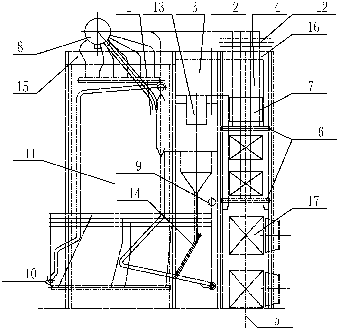
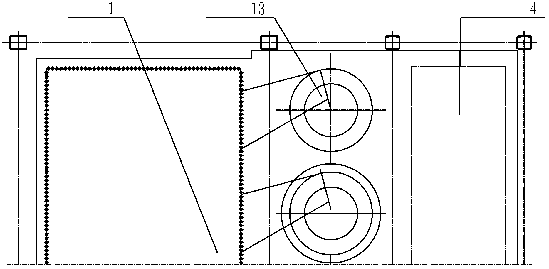
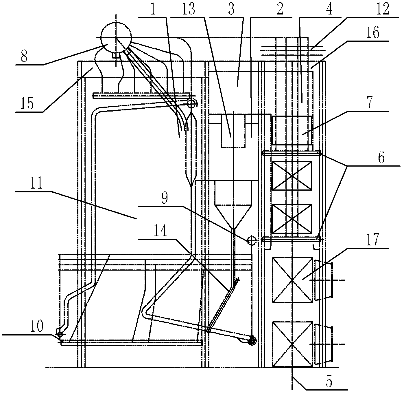
[0013] like Figure 1~Figure 2 Shown: The structure of the forced circulation hot water boiler includes furnace 1, cyclone separator 2, horizontal flue 3, tail shaft 4, flue gas outlet 5, economizer header 6, economizer 7, drum 8, return water Distribution header 9, water wall header 10, water wall 11, hot water outlet header 12, separator 13, fly ash backburning pipeline 14, front top plate 15, rear top plate 16, air preheater 17, etc.

[0014] The present invention comprises a furnace 1, a cyclone separator 2 is arranged at the outlet of the furnace 1, the outlet end of the cyclone separator 2 communicates with a horizontal flue 3, a tail shaft 4 is arranged on one side of the horizontal flue 3, and a tail shaft 4 is arranged on the tail shaft 4 An economizer 7 is installed in the center, an air preheater 17 is installed at the bottom of the tail shaft 4, and the lower part...


PUM


Abstract

The invention relates to a forced circulation type hot water boiler structure which comprises a hearth and is characterized in that a cyclone separator is arranged at the outlet of the hearth, the outlet end of the cyclone separator is communicated with a horizontal flue, a tail vertical shaft is arranged at one side of the horizontal flue, an economizer is installed in the tail vertical shaft, an air preheater is installed at the bottom part of the tail vertical shaft, and a flue gas outlet is arranged at the lower part of the air preheater; and a water cooling wall is arranged at the periphery of the hearth, a water inlet of the water cooling wall is connected with a water cooling wall header at the lower part of the water cooling wall, the water cooling wall header is connected with a backwater distribution header via a connecting pipe, a water outlet at the upper end of the water cooling wall is connected with a boiler barrel at the upper end of the hearth, the boiler barrel is connected with an economizer header at the lower part of the economizer by a connecting pipe, and the economizer header is connected with a hot water outlet header at the top end of the tail vertical shaft via a connecting pipe. According to the forced circulation type hot water boiler structure, the height of the tail vertical shaft is decreased, the height of the hearth is decreased, the metal consumption quantity of the boiler main body is reduced, the imperfect combustion loss of the boiler machinery is reduced, and the boiler efficiency is improved.

Description

technical field [0001] The invention relates to a forced circulation hot water boiler structure, in particular to a hot water boiler for medium and large capacity. Background technique [0002] Due to the continuous advancement of the national energy-saving policy, the penetration rate of central heating in the northern region is getting higher and higher, and hot water is mostly used as the heating medium, so hot water boilers are widely used. Based on the comprehensive consideration of boiler room construction and boiler operating costs, the combustion equipment of medium and large capacity hot water boilers (29MW~70MW) mostly adopts a layer-fired grate structure. As far as the furnace circulation mode is concerned, there are natural circulation and forced circulation. The water process of forced circulation is as follows: the return water first enters the lower header of the water wall from the bottom distribution header, is heated in the water wall of the furnace, then ...

Claims


Application Information

Patent Timeline
Patent Type & Authority Applications(China)
IPC IPC(8): F24H1/40
Inventor 邹娴王彬
Owner WUXI HUAGUANG IND BOILER
Learn More