Transmission for electric vehicles
A technology of transmission and electric vehicle, which is applied in the direction of transmission, gear transmission, transmission control, etc., can solve the problems of easy burnout of motor and control system, and reduced power and torque.
- Summary
- Abstract
- Description
- Claims
- Application Information
AI Technical Summary
Problems solved by technology
Method used
Image

Examples
Embodiment 1
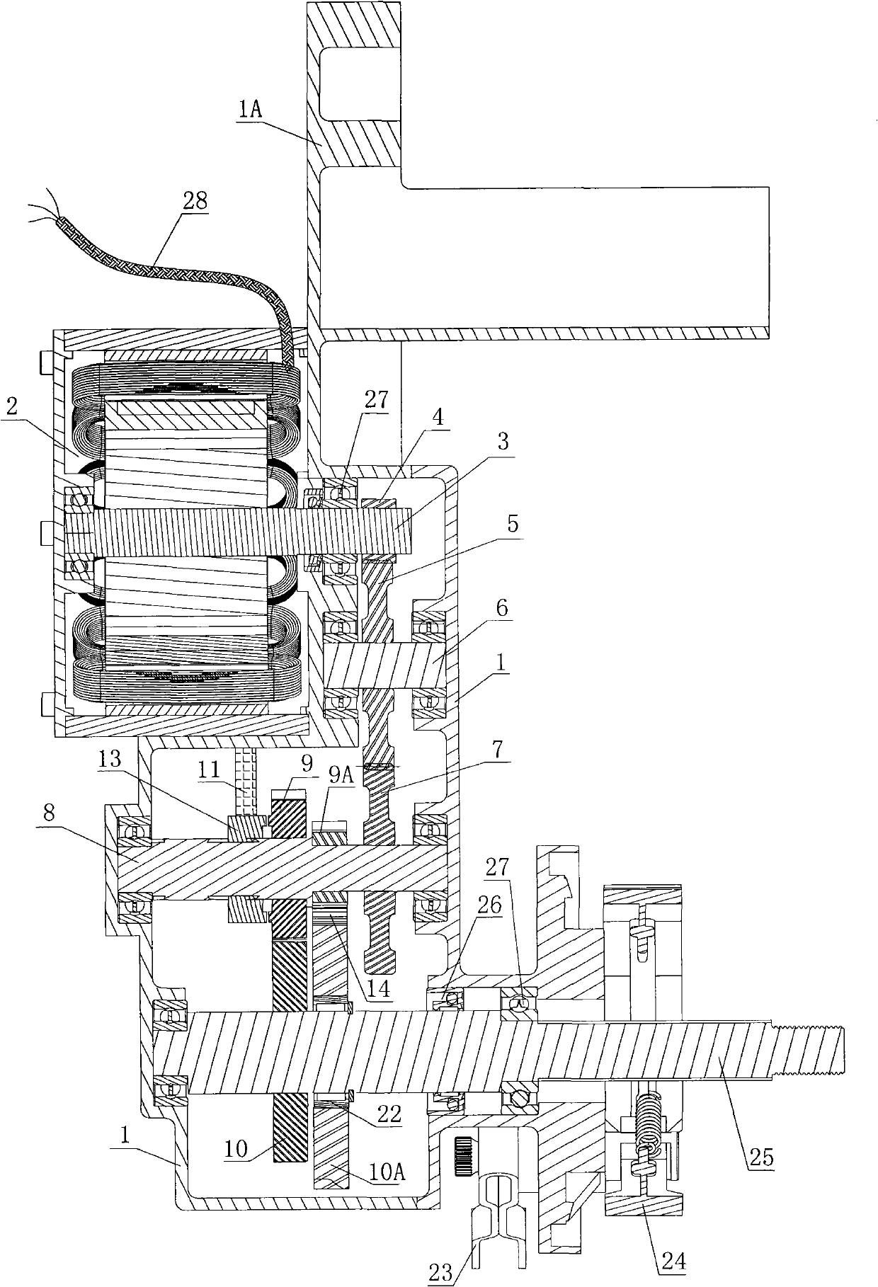
[0036] Such as Figure 1 to Figure 5 Shown is the first embodiment of the electric vehicle transmission of the present invention. The electric vehicle transmission includes a box body 1 and related transmission mechanisms. The box body 1 is connected with a flat fork 1A, and the flat fork 1A is used to connect the entire machine on the on the frame.
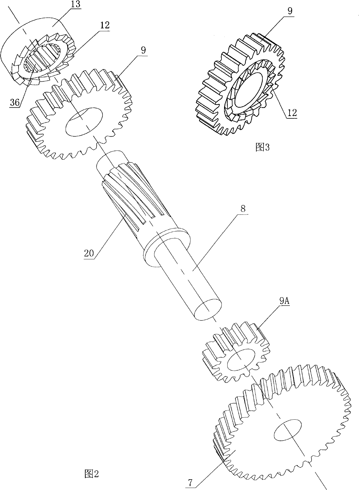
[0037] After the motor 2 is energized and rotated, the motor shaft gear 4 at the end of the motor shaft 3 drives the bridge gear 5 to rotate, and the bridge gear 5 meshes with the main shaft input gear 7 to rotate so as to drive the main shaft 8 to rotate.
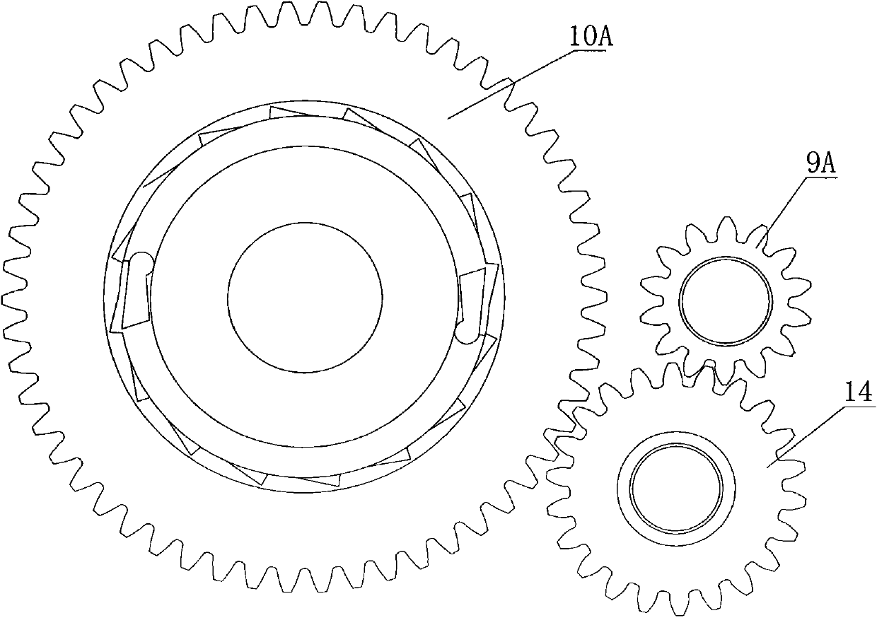
[0038] Such as figure 1As shown in , the output shaft 25 is provided with a first-gear output gear 10A and a second-gear output gear 10, the second-gear output gear 10 is fixed on the output shaft 25, and the first-gear output gear 10A is sleeved on the output shaft 25. A one-way clutch 22 is arranged between the gear output gear 10A and the output shaft 25, and the diamete...
Embodiment 2
[0043] Such as Figure 6 to Figure 10 Shown is the second embodiment of the electric vehicle transmission of the present invention. The electric vehicle transmission includes a box body 1 and related transmission mechanisms. The box body 1 is connected with a flat fork 1A, and the flat fork 1A is used to connect the entire machine on the on the frame.
[0044] After the motor 2 is energized and rotated, the motor shaft gear 4 at the end of the motor shaft 3 drives the bridge gear 5 to rotate, and the bridge gear 5 meshes with the main shaft input gear 7 to rotate so as to drive the main shaft 8 to rotate.
[0045] When the motor drives the main shaft 8 and the first gear driving gear 9A to rotate clockwise, the moving part 15 is separated from the second gear driving gear 9 under the action of the separation spring 17, and the power of the main shaft 8 cannot be transmitted to the second gear driving gear 9. The spindle is idling. Such as Figure 4 As shown, the first gear ...
Embodiment 3
[0049] Such as Figure 11 to Figure 15 Shown is the third embodiment of the electric vehicle transmission of the present invention. The electric vehicle transmission includes a box body 1 and related transmission mechanisms. The box body 1 is connected with a flat fork 1A, and the flat fork 1A is used to connect the entire machine on the on the frame.
[0050] After the motor 2 is energized and rotated, the motor shaft gear 4 at the end of the motor shaft 3 drives the bridge gear 5 to rotate, and the bridge gear 5 meshes with the main shaft input gear 7 to rotate so as to drive the main shaft 8 and the two driving gears to rotate.
[0051] When the motor drives the main shaft 8, the first gear driving gear 9A and the second gear driving gear 9 to rotate clockwise, the two driving gears drive the output gear to rotate, and the moving part 15 is separated from the driven part 21 under the action of the separation spring 17 At this time, the power of the first gear output gear 1...
PUM
 Abstract
Description
Claims
Application Information
 - R&D
- Intellectual Property
- Life Sciences
- Materials
- Tech Scout
- Unparalleled Data Quality
- Higher Quality Content
- 60% Fewer Hallucinations
Browse by: Latest US Patents, China's latest patents, Technical Efficacy Thesaurus, Application Domain, Technology Topic, Popular Technical Reports.
© 2025 PatSnap. All rights reserved.Legal|Privacy policy|Modern Slavery Act Transparency Statement|Sitemap|About US| Contact US: help@patsnap.com