Capacity-varying rotary type compressor
A technology of rotary compressors and compression mechanisms, which is applied in the direction of rotary piston machines, rotary piston pumps, mechanical equipment, etc., and can solve problems such as limited application range, technical difficulties in stationary sliding vanes, and difficulty in stopping the movement of sliding vanes. , to achieve the effect of easy promotion and application
- Summary
- Abstract
- Description
- Claims
- Application Information
AI Technical Summary
Problems solved by technology
Method used
Image
Examples
Embodiment 1
[0066] In this embodiment, two slide vanes consisting of a first slide vane and a second slide vane, and exhaust holes adjacent to each slide vane are arranged in one cylinder. When the first slide is in motion, the movement of the second slide is interrupted, which is called mode A. Conversely, when the movement of the first slide is interrupted, the second slide moves, which is called mode B. Due to the existence of these two modes, a variable capacity rotary compressor with two-stage displacement control can be performed.
[0067] Hereinafter, the specific content of this Embodiment 1 is demonstrated according to drawing.
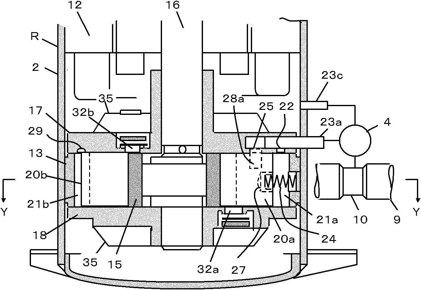
[0068] see figure 1 , is a longitudinal section view of a rotary compressor with two vanes in one cylinder, showing its internal structure.
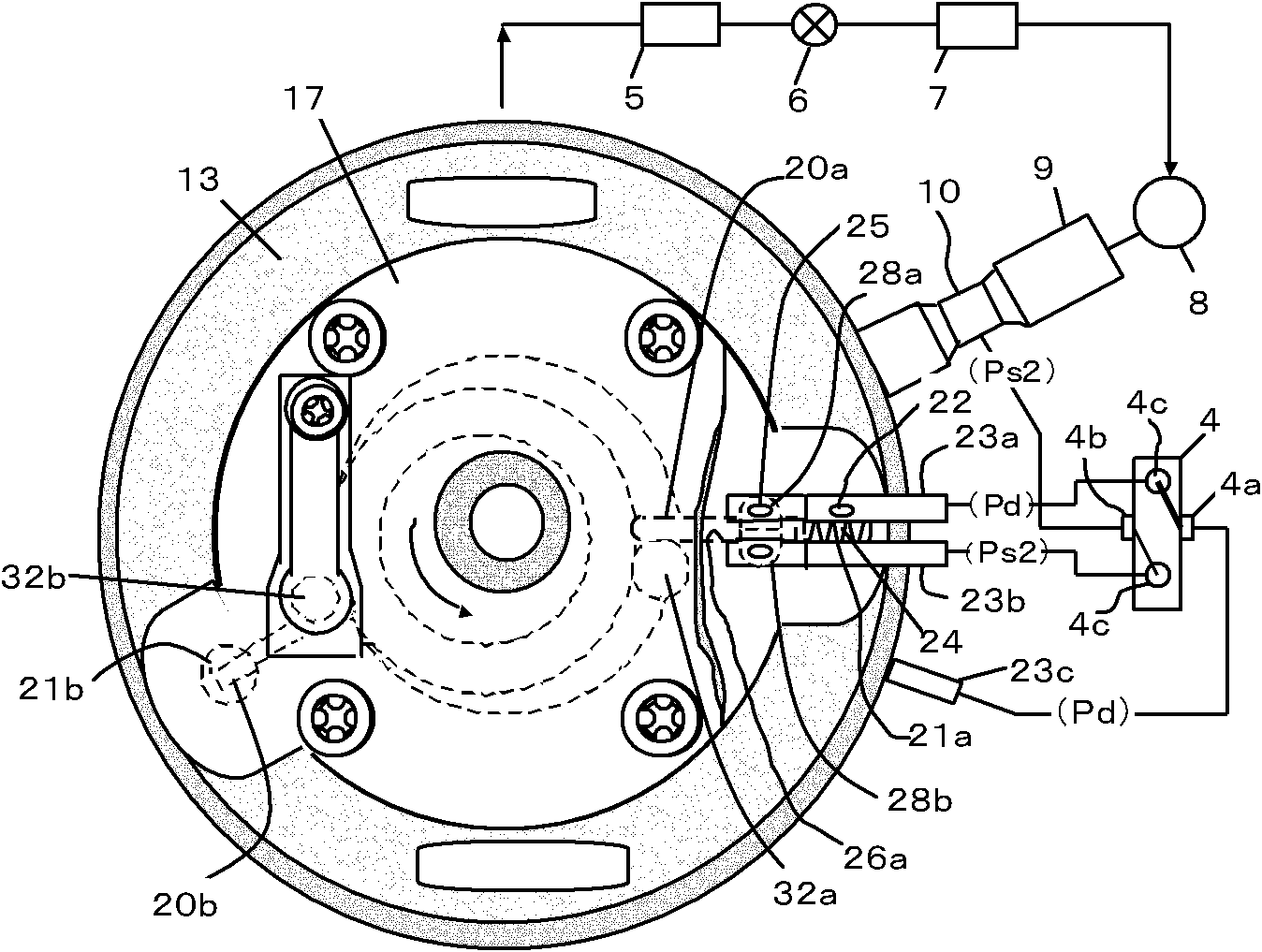
[0069] see figure 2 ,for figure 1 The cross-sectional view taken along the Y-Y line in FIG. 2 shows an example of a cross-section of the above-mentioned rotary compressor and a refrigeration cycle system equi...
Embodiment 2
[0124] In Embodiment 1, different pressures are applied to the left and right sliding sides of the first sliding piece 20a sliding on the side wall of the first sliding piece groove 26a, so that the first sliding piece 20a is limited to the first sliding surface. slide slot 26a to stop it. In Embodiment 2, the purpose is to apply different pressures on the upper and lower sliding sides of the first sliding piece 20a to make the first sliding piece 20a stationary toward the main bearing 17 or the auxiliary bearing 18 .
[0125] see Figure 8 , the first connecting pipe 23a and the second connecting pipe 23b are mounted on the outer peripheries of the main bearing 17 and the sub-bearing 18, respectively. Communication holes 25 communicating with the first connecting pipe 23 a and the second connecting pipe 23 b are respectively provided at the tips thereof. The two communication holes 25 respectively open toward the upper and lower sliding sides of the first sliding piece 20a....
Embodiment 3
[0130] see Figure 9 , the present embodiment 3 is an embodiment in which the rotary compressor R disclosed in the embodiment 1 is mounted in a heating and cooling air conditioner having a four-way valve.
[0131] The first connecting pipe 23a of the rotary compressor R communicates with point S between the four-way valve and the heat exchanger 41 on the system, and the second connecting pipe 23b communicates with T between the four-way valve 4 and the heat exchanger 43 point.
[0132] As a result, during the heating operation, point S is on the high pressure side and point T is on the low pressure side, so the operation of the rotary compressor R is in mode A. During cooling operation, point S is the low-pressure side, and point T is the high-pressure side. Therefore, the rotary compressor R operates in mode B, and the capacity of the compressor decreases.
[0133] In Embodiment 3, the four-way valve required in the heating and cooling air conditioner is used, so the four-w...
PUM
 Abstract
Description
Claims
Application Information
 - R&D
- Intellectual Property
- Life Sciences
- Materials
- Tech Scout
- Unparalleled Data Quality
- Higher Quality Content
- 60% Fewer Hallucinations
Browse by: Latest US Patents, China's latest patents, Technical Efficacy Thesaurus, Application Domain, Technology Topic, Popular Technical Reports.
© 2025 PatSnap. All rights reserved.Legal|Privacy policy|Modern Slavery Act Transparency Statement|Sitemap|About US| Contact US: help@patsnap.com


