
Connection component for upright post and cross beam

A technology for connecting components and connecting parts, which is applied to building components, door/window protection devices, fences, etc., can solve the problems of inconvenient installation and disassembly, many U-shaped joint consumables, low connection stability and low connection strength, etc. Stable and reliable connection, strong connection stability and reliability, material saving effect

Active Publication Date: 2012-07-11
HUNAN GOLDWELL NEW MATERIALS TECH CO LTD
View PDF8 Cites 6 Cited by
  • Summary
  • Abstract
  • Description
  • Claims
  • Application Information

AI Technical Summary

Problems solved by technology

The existing connectors for columns and beams are generally U-shaped joints or L-shaped joints, wherein the U-shaped joints are placed inside the pipe during installation, which makes installation and disassembly extremely inconvenient, and the U-shaped joints consume more materials , while the L-shaped connector has less consumables, but its connection stability and connection strength are low

Method used


Image

  • Connection component for upright post and cross beam
  • Connection component for upright post and cross beam
  • Connection component for upright post and cross beam

Examples


Embodiment 1

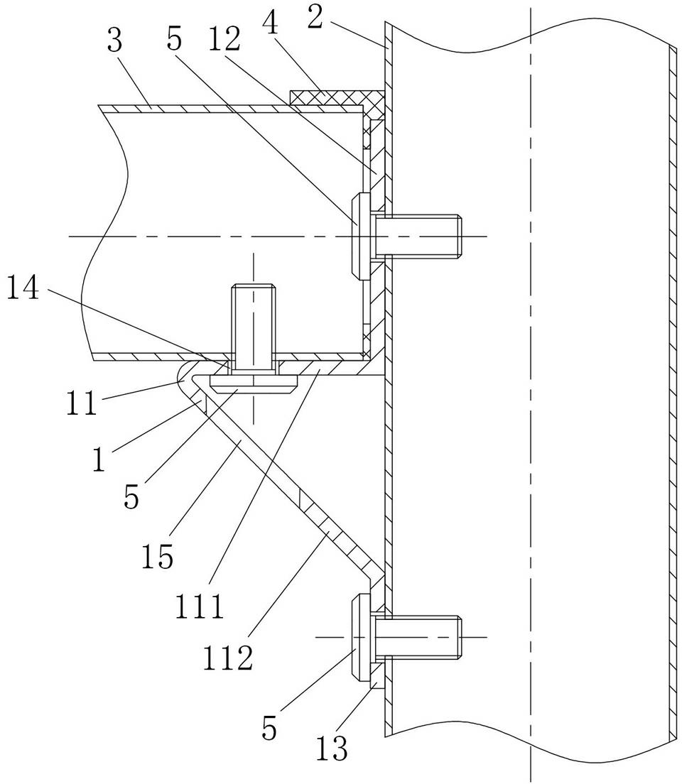
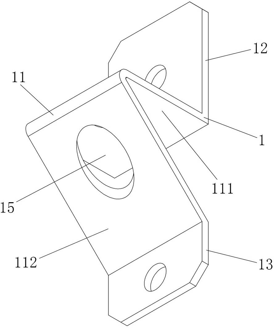
[0020] figure 1 and figure 2 Shown is the first embodiment of the connecting assembly for the column and the crossbeam of the present invention, the connecting assembly of this embodiment includes a connector body 1, and the connector body 1 includes an upper column connecting portion 12, a lower column connecting portion 13 and a connection In the beam connecting portion 11 between the upper column connecting portion 12 and the lower column connecting portion 13, the beam connecting portion 11 includes a supporting edge 111 and an oblique supporting edge 112, and the supporting edge 111 is connected to the lower end of the upper column connecting portion 12 and along the The direction in which the crossbeam 3 is arranged extends outward, and one end of the inclined support side 112 is connected to the upper end of the lower column connection part 13. The inclined support side 112 is arranged obliquely upward and connected with the supporting side 111. After the fastener 5 i...

Embodiment 2

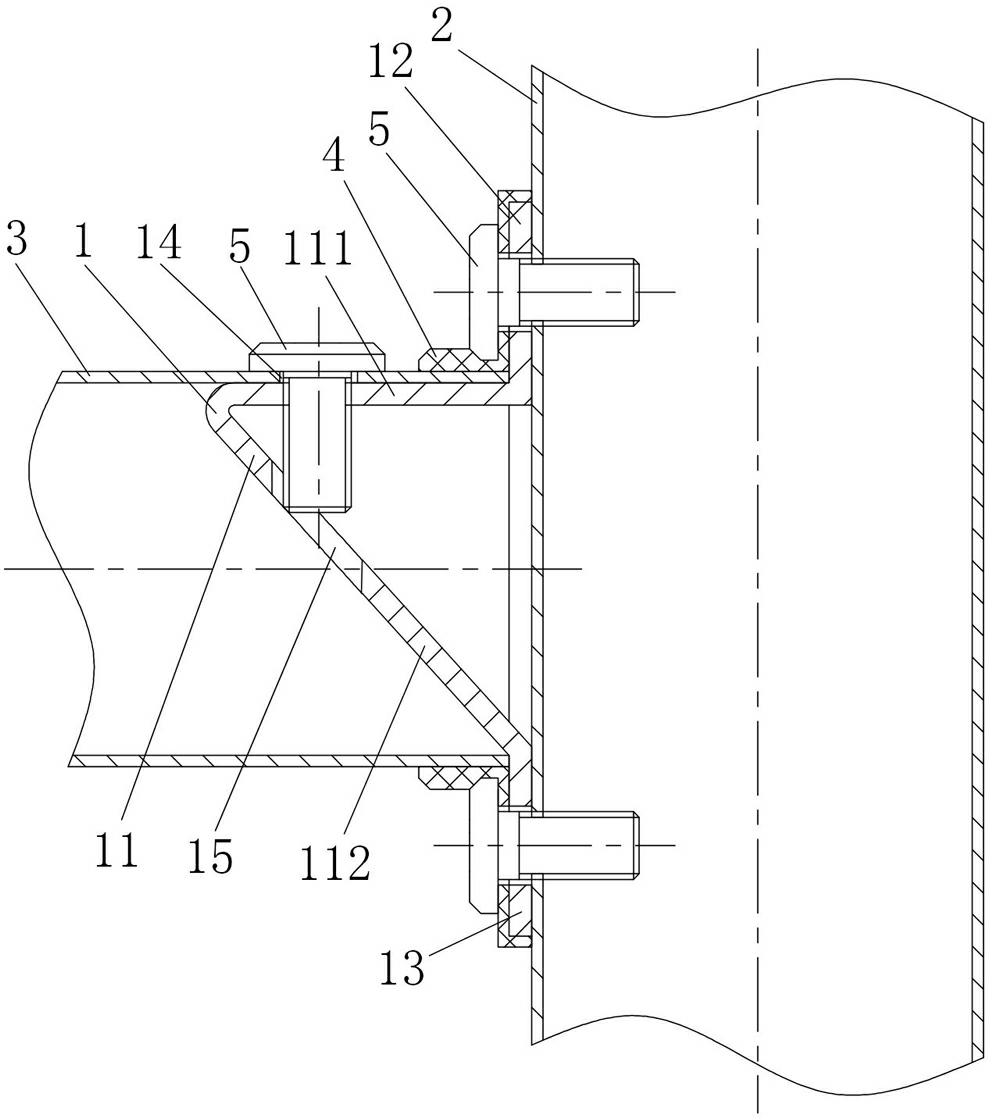
[0024] image 3 and Figure 4 It shows the second embodiment of the connecting assembly for columns and beams of the present invention, the connector body 1 in this embodiment is basically the same as the connector body 1 in Embodiment 1, the difference is that when the beam 3 is installed, The beam connecting part 11 is inserted in the beam 3, the upper column connecting part 12 and the lower column connecting part 13 protrude from the upper end and the lower end of the beam 3 respectively, and the supporting edge 111 holds the upper end of the inner wall of the beam 3 and passes the fastener 5 Linked to the upper wall of the beam 3, the fastener 5 passes through the upper arm of the beam 3 and the fastener installation hole 14 from the top of the beam 3 to connect with the supporting edge 111, and the fastener avoidance hole 15 on the inclined support edge 112 can prevent When the fastener 5 is too long, it interferes with the inclined support edge 112 .

[0025] Also be p...


PUM


Abstract

The invention discloses a connection component for an upright post and a cross beam. The connection component comprises a connecting piece body, wherein the connecting piece body comprises an upper upright post connecting part, a lower upright post connecting part and a cross beam connecting part which is connected between the upper upright post connecting part and the lower upright post connecting part; the cross beam connecting part comprises a cross beam supporting edge which can be connected with the cross beam through a fastening piece and a tilted supporting edge which is connected between the cross beam supporting edge and the lower upright post; and the upright post connecting part is connected with the cross beam supporting edge. The connection component has the advantages of simple structure, low material consumption, easy production, high connection stability and the like.

Description

technical field [0001] The invention relates to an assembly fitting used for connecting pipes, in particular to a connecting assembly used for columns and beams. Background technique [0002] When assembling protective nets, protective windows and fences, two pipes (generally divided into columns and beams) are generally connected by connecting pieces. The existing connectors for columns and beams are generally U-shaped joints or L-shaped joints, wherein the U-shaped joints are placed inside the pipe during installation, which makes installation and disassembly extremely inconvenient, and the U-shaped joints consume more materials , while the L-shaped joint has less consumables, but its connection stability and connection strength are low. Contents of the invention [0003] The technical problem to be solved by the present invention is to overcome the deficiencies of the prior art and provide a connection assembly for columns and beams with simple structure, less consumab...

Claims


Application Information

Patent Timeline
Patent Type & Authority Applications(China)
IPC IPC(8): E04B1/58E06B9/00E04H17/14
Inventor 谢斌泉
Owner HUNAN GOLDWELL NEW MATERIALS TECH CO LTD
Learn More