Device and method for producing biogas by supplying boiler tail gas as heat source to anaerobic tank

An anaerobic pool and heat source technology, applied in biochemical equipment and methods, biochemical cleaning devices, enzymology/microbiology devices, etc., can solve problems such as high cost, waste of energy, and environmental pollution by heat island effect, and achieve environmental protection , avoid waste, and facilitate operation

Active Publication Date: 2012-07-11
四川华宇瑞得科技有限公司
View PDF6 Cites 7 Cited by
  • Summary
  • Abstract
  • Description
  • Claims
  • Application Information

AI Technical Summary

Problems solved by technology

[0002] In the current pure grain solid-state fermentation liquor brewing process, the distillation process requires a large amount of external energy supply (natural gas, coal, etc.) as fuel heating, heating the bottom pot water to generate steam distilled distiller's grains to produce liquor, and a large amount of high-temperature tail gas is discharged during the fuel combustion process. Under the existing production equipment and methods, the high-temperature tail gas is directly discharged, causing the heat island effect to pollute the environment. In the existing brewing process, a large amount of sewage (bottom pot water, site washing sewage, cellar red water, etc.) is discharged during the brewing process. At the same time About one retort for every ten retorts per group is discarded every day. At present, some capable production enterprises use microbial anaerobic fermentation to treat sewage to generate biogas. method, but the high-temperature anaerobic bacteria require a higher temperature of 55±1°C in the fermenter. If the heating cost is very high through external heat energy, there is no promotion value and practical value), and discarding the waste grains as feed into the breeding industry is wasteful. a lot of energy

Method used


Image

  • Device and method for producing biogas by supplying boiler tail gas as heat source to anaerobic tank
  • Device and method for producing biogas by supplying boiler tail gas as heat source to anaerobic tank

Examples


Embodiment Construction

[0023] The present invention will be further described below in conjunction with accompanying drawing.

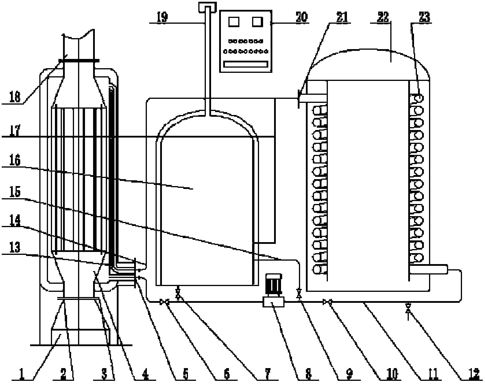
[0024] like figure 1 As shown, the present invention includes an anaerobic tank 22, and also includes a low-temperature flue heat exchanger 4, a heat exchanger 23 arranged on the anaerobic tank 22, a delivery pipeline 11 and a heat exchange circulation motor 8 arranged on the delivery pipeline 11 , the low-temperature flue heat exchanger 4 is provided with a high-temperature exhaust gas input port, a high-temperature heat source output port 5 and a medium inlet 13, and the delivery pipeline 11 is connected to the high-temperature heat source output port 5 and the inlet of the heat exchanger 23 . During installation, the low-temperature flue heat exchanger connecting flange 3 of the low-temperature flue heat exchanger 4 is connected to the connecting flange 2 of the boiler exhaust outlet, so that the low-temperature flue heat exchanger 4 and the boiler exhaust outlet 1 The...


PUM


Abstract

The invention discloses a biogas production device, and especially a device for producing biogas by supplying boiler tail gas as a heat source to an anaerobic tank in wine brewing process. The invention provides a device for producing biogas by supplying boiler tail gas as a heat source to an anaerobic tank, which can increase the energy utilization rate, comprises an anaerobic tank, and also comprises a low-temperature flue heat exchanger, a heat exchanger disposed on the anaerobic tank, a conveying pipeline, and a heat exchange cycle motor disposed on the conveying pipeline; a high-temperature tail gas input port, a high-temperature heat source output interface, and a medium inlet are disposed on the low-temperature flue heat exchanger; the high-temperature heat source output interface is communicated with an inlet of the heat exchanger through the conveying pipeline. The anaerobic tank is heated by boiler high-temperature tail gas, which not only makes use of boiler waste heat, but also makes use of waste residues in wine brewing process; not only the environment is protected, but also a lot of biogas is obtained; and the method for waste treatment in wine brewing process is the best of both worlds.

Description

technical field [0001] The invention relates to a biogas production device, in particular to a device in which boiler tail gas is used as a heat source to supply an anaerobic pond to generate biogas during the brewing process. In addition, the present invention also relates to a biogas production method, especially a method in which boiler tail gas is used as a heat source to supply anaerobic ponds to generate biogas. Background technique [0002] In the current pure-grain solid-state fermentation liquor brewing process, the distillation process requires a large amount of external energy supply (natural gas, coal, etc.) as fuel heating, heating the bottom pot water to generate steam distilled distiller's grains to produce liquor, and a large amount of high-temperature tail gas is discharged during the fuel combustion process. Under the existing production equipment and methods, the high-temperature tail gas is directly discharged, causing the heat island effect to pollute th...

Claims


Application Information

Patent Timeline
Patent Type & Authority Applications(China)
IPC IPC(8): C12M1/38C12M1/36C12M1/34C12M1/107C12M1/02C12P5/02
CPCY02E50/343C12M21/04C12M41/18Y02E50/30Y02P20/129
Inventor 魏华海范润黎廖泽刚魏先勇谭万虎
Owner 四川华宇瑞得科技有限公司
Why Eureka
Try Eureka