Water jet cutting actuating device

An actuator and water jet technology, applied in metal processing, etc., can solve problems such as inconvenient disassembly, difficult cutting, difficult transportation, etc., and achieve the effects of easy storage, space saving, and levelness assurance

Active Publication Date: 2014-03-26
NUCLEAR POWER INSTITUTE OF CHINA
View PDF9 Cites 0 Cited by
  • Summary
  • Abstract
  • Description
  • Claims
  • Application Information

AI Technical Summary

Problems solved by technology

However, even if a large-scale machine tool with a plane degree of freedom of 4-8m is formed, the stroke of its vertical degree of freedom is limited to 1.6m, which cannot meet the vertical cutting stroke of a large shield; in addition, CNC machine tools have strong processing pertinence , it is usually only suitable for the processing of a certain type of parts, and it is difficult to achieve arbitrary shape cutting; finally, the integrated design of CNC machine tools makes it inconvenient to disassemble and transport difficult, making it limited to fixed locations

Method used


Image

  • Water jet cutting actuating device
  • Water jet cutting actuating device
  • Water jet cutting actuating device

Examples


Embodiment 1

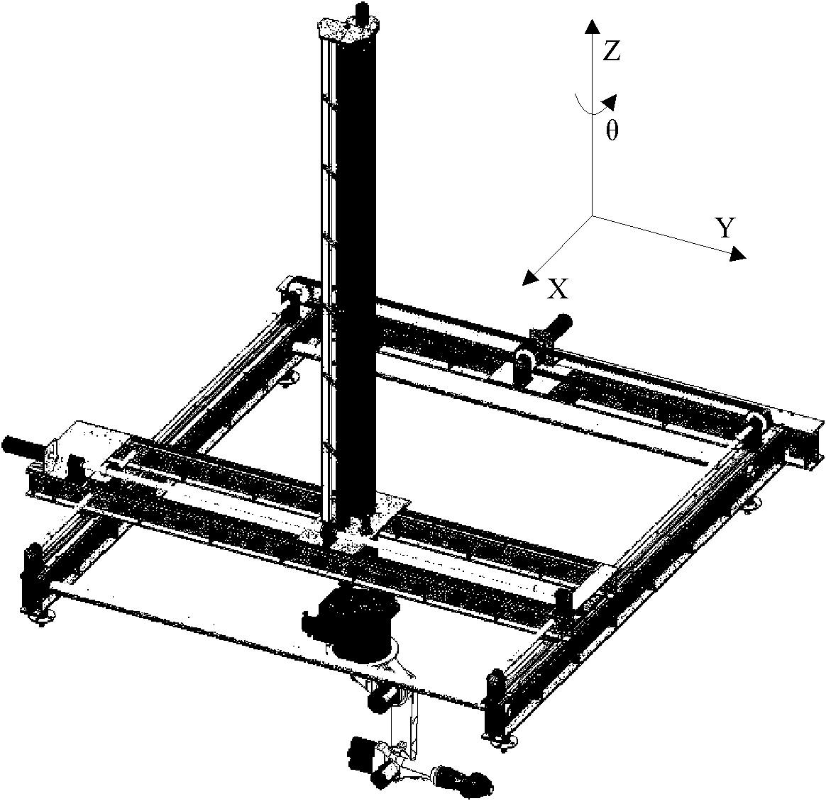
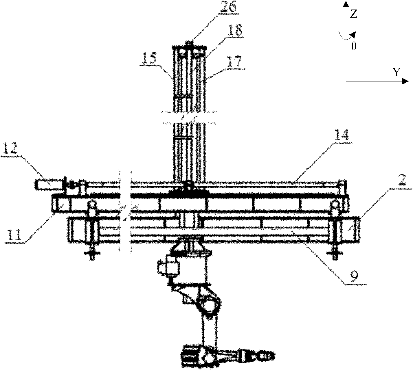
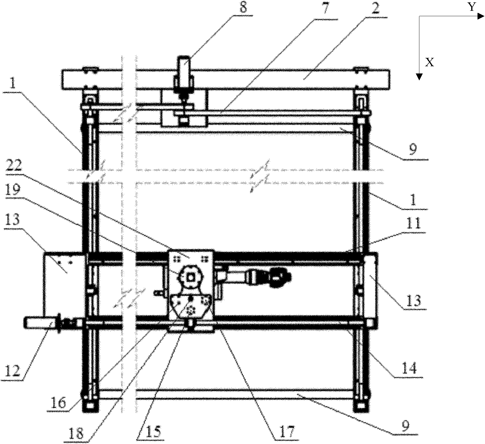
[0045] like Figure 1~3 As shown, a water jet cutting execution device of the present invention includes an X-direction movement module, a Y-direction movement module, a Z-direction movement module, a θ-direction movement module and a water jet cutting machine. The X-direction movement module is mainly composed of the X-direction support beam 1 and the first motor beam 2, the Y-direction movement module is mainly composed of the Y-direction motor beam 11 and the second motor beam, and the Z-direction movement module is mainly composed of the Z-direction support rod 15 and the guide rail. The support rod 16, the guide rod 17, the Z-direction ball screw 18, and the outer cylinder 19 are composed, and the θ-direction movement module is mainly composed of the inner cylinder 25 and the θ-direction motor 26. Its overall positional relationship is: with the X-direction movement module as the base, the Y-direction movement module is supported on the X-direction movement module, which ...

Embodiment 2

[0062] The difference between this embodiment and embodiment 1 is:

[0063]The X-direction movement module also includes two horizontal adjustment rods 9 and four vertical adjustment nuts 10 . Among them, two horizontal adjustment rods 9 are installed between the two X-direction support beams 1 in a direction perpendicular to the X-direction support beam 1, and the two horizontal adjustment rods 9 are respectively located at the first and last ends of the X-direction support beam 1; The vertical adjustment nuts 10 are respectively installed on the lower ends of the two X-direction support beams 1 . In addition, height-adjustable rack legs can also be respectively installed under the vertical adjustment nuts 10 .

[0064] The horizontal adjustment rod 9 can not only adjust the distance between the two ends of the two X-direction support beams 1 according to the actual situation, thereby adjusting their parallelism, but also can play the role of strengthening the X-direction mo...

Embodiment 3

[0066] The difference between this embodiment and the above two embodiments is:

[0067] The inner wall of the guide cylinder 20 in the Z-direction movement module is interference-fitted with a liner. The material of the liner is preferably polytetrafluoroethylene, and the inner wall may have several rectangular grooves.

[0068] This design can not only reduce the friction between the outer cylinder 19 and the guide cylinder 20, but also guide the attached water of the outer cylinder 19 back to the pool through the rectangular groove when the outer cylinder 19 is lifted to the guide cylinder 20 after the water cutting is completed. .


PUM


Abstract

The invention belongs to the technical field of cutting control, and particularly relates to a water jet cutting control device, which comprises an X-direction moving module, a Y-direction moving module, a Z-direction moving module, a theta-direction moving module and a cutting device. The X-direction moving module is used as a base, the Y-direction moving module is supported on the X-direction moving module and can integrally slide in an X-direction, the Z-direction moving module is supported on the Y-direction moving module, not only can integrally slide in a Y-direction, but also can slide in the X-direction along with the Y-direction moving module, and can also slide in a Z-direction by the aid of a self component of the Z-direction moving module, the theta-direction moving module is positioned inside the Z-direction moving module and can rotate, and the cutting device is connected to the lower end of the theta-direction moving module. The water jet cutting control device solves technical problems that degrees of freedom of an existing water jet cutting device are few and a vertical cutting stroke of the existing water jet cutting device is short, and technical effects with multiple degrees of freedom, a long vertical cutting stroke and convenience in transportation and assembly are realized.

Description

technical field [0001] The invention belongs to the technical field of cutting control, and in particular relates to a water jet cutting execution device. Background technique [0002] Due to the high-efficiency and cold-state characteristics of water jet cutting, the water jet cutting machine can achieve deep penetration and all-round cutting of various soft and hard materials with its high energy density, good jet controllability and material adaptability , has a wide range of applications in industry. [0003] It should be noted that the existing water jet cutting machines can only perform plane cutting based on two degrees of freedom, and cannot cut large shields in any orientation and shape. [0004] CNC machines widely used in industrial production have multiple degrees of freedom and can process and cut workpieces in all directions. However, even if a large-scale machine tool with a plane degree of freedom of 4-8m is formed, the stroke of its vertical degree of free...

Claims


Application Information

Patent Timeline
Patent Type & Authority Patents(China)
IPC IPC(8): B26F3/00
Inventor 吕仙镜司丹丹廖玮汪海黄冈韩富仁童明炎潘隆轩杜双
Owner NUCLEAR POWER INSTITUTE OF CHINA
Why Eureka
Try Eureka