
Loading and unloading manipulator

A manipulator and unloading mechanism technology, applied in manipulators, program-controlled manipulators, metal processing equipment, etc., can solve the problems of increased labor costs, high work intensity, low workpiece processing efficiency, etc., to reduce labor and production costs, Avoid personal safety accidents and meet the effect of mass production

Inactive Publication Date: 2012-07-11
SUZHOU YUEHAI STRETCHING MACHINERY
View PDF4 Cites 39 Cited by
  • Summary
  • Abstract
  • Description
  • Claims
  • Application Information

AI Technical Summary

Problems solved by technology

Due to the different shapes, sizes, and weights of workpieces to be processed, for workpieces with relatively large volume and weight, many operators may be required to operate at one station, which increases labor costs and is inconvenient for personnel coordination; and , the operator must be able to use both eyes and hands during the operation, with a high degree of concentration, and a little carelessness will cause personal safety accidents
In addition, due to the influence of manpower, space and other factors, the efficiency of workpiece processing is very low, and the work intensity of personnel is high. Not only the quality of products cannot be effectively guaranteed, but it is also difficult to meet the needs of mass production in modern industries.

Method used


Image

  • Loading and unloading manipulator
  • Loading and unloading manipulator
  • Loading and unloading manipulator

Examples


Embodiment Construction

[0018] The present invention will be further described in detail below in conjunction with the accompanying drawings and specific embodiments.

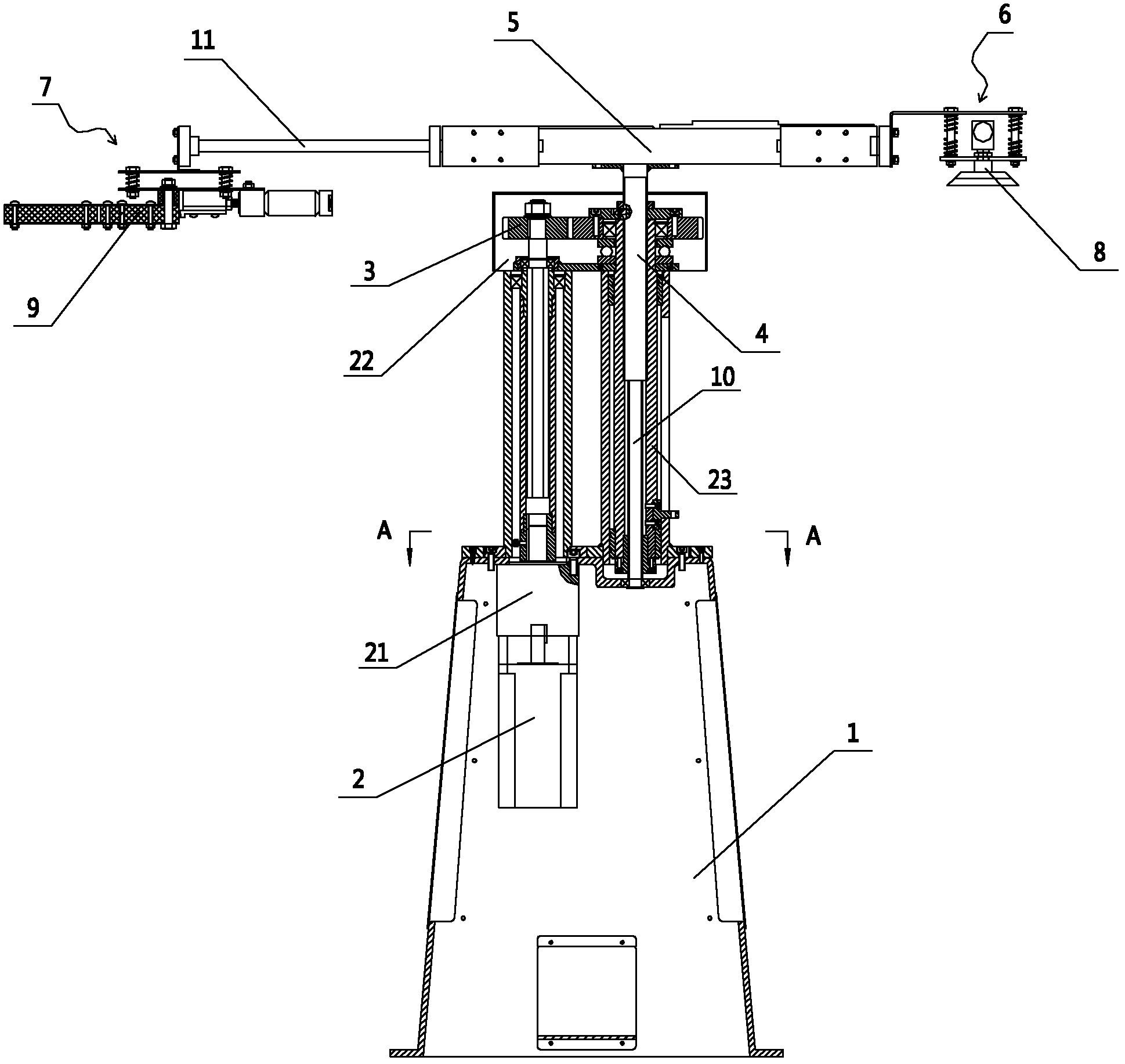
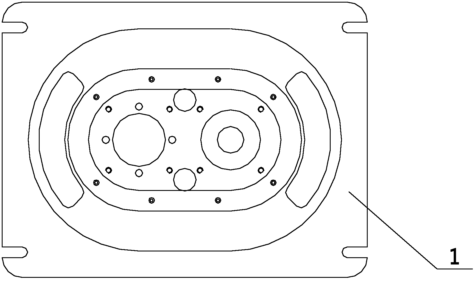
[0019] attached Figure 1-3 It is a kind of loading and unloading manipulator described in the present invention, comprises workbench 1, motor 2, deceleration device 21, gear box 22, rotating shaft 4, rotary platform 5, feeding mechanism 6, unloading mechanism 7; Said motor 2 Controlled by a controller (not shown in the figure), and the motor 2 is fixed in the workbench 1; the input end of the reduction gear 21 is connected to the motor 2, and the output end is connected to the gear pair 3 in the gearbox 22; the gear pair The other end of 3 is connected to the rotating shaft 4; the rotating shaft 4 is placed vertically, and it is arranged above the workbench 1 through a screw mandrel 10; the outer side of the screw mandrel 10 is fixed with a protective cover 23, and the protective cover 23 is fixed Above the workbench 1; a rotating t...


PUM


Abstract

The present invention relates to a loading and unloading manipulator which is characterized by comprising a workbench, a motor, a speed reducing device, a rotating shaft, a rotating platform, a loading mechanism and an unloading mechanism. The motor is controlled by a controller and fixed in the workbench; the input end of the speed reducing device is connected with the motor, and the output end is connected with a gear pair in a gear box; the other end of the gear pair is connected with the rotating shaft; the rotating shaft is arranged vertically; two ends of the rotating shaft are arranged above the workbench through screws; one rotating platform is fixed on the top end of the rotating shaft, and the rotating platform is perpendicular to the rotating shaft; the loading mechanism and the unloading mechanism are fixed on two ends of the rotating platform; the loading mechanism is a sucking disc; and the unloading mechanism is a clamping claw. Due to the adoption of the loading and unloading manipulator during the mechanical processing, the manpower and the production cost are reduced effectively, the occurrence of personal safety accident in the production process is avoided, the requirement of the mass production of the modern industry is met, the production efficiency is improved, and the great economic benefits are brought to the manufacturers.

Description

technical field [0001] The invention relates to a loading and unloading device for mechanical processing, in particular to a loading and unloading manipulator, which belongs to the field of equipment for stamping and forming processing of sheet metal. Background technique [0002] In the current stamping processing industry, it is generally an assembly line operation, that is, an operating station is installed on the front side of the processing equipment, and the raw materials are placed in the processing equipment. After stamping and forming, the finished processing is taken out from the processing equipment. artifact. Due to the different shapes, sizes, and weights of workpieces to be processed, for workpieces with relatively large volume and weight, many operators may be required to operate at one station, which increases labor costs and is inconvenient for personnel coordination; and , The operator must use both eyes and hands during the operation, with a high degree o...

Claims


Application Information

Patent Timeline
Patent Type & Authority Applications(China)
IPC IPC(8): B25J9/08B21D43/00B21D43/02
Inventor 韩建国
Owner SUZHOU YUEHAI STRETCHING MACHINERY
Learn More