Belt type roller magnetic separator

A magnetic separator and roller technology, applied in the field of magnetic separators, can solve the problems of wasting limited resources, low magnetic separation efficiency, and large power consumption, and achieve high magnetic separation efficiency, improved magnetic separation efficiency, and large conveying capacity Effect

Inactive Publication Date: 2012-07-11
周国发
View PDF4 Cites 8 Cited by
  • Summary
  • Abstract
  • Description
  • Claims
  • Application Information

AI Technical Summary

Problems solved by technology

[0002] At present, there are belt magnetic separators, drum magnetic separators, roller magnetic separators, disc magnetic separators, ring magnetic separators, cage magnetic separators and pulley magnetic separators in mining plants. The machine requires multiple sets of technological processes for magnetic separation, which consumes a lot of power and the efficiency of magnetic separation is low. There will always be more iron powder flowing into the tailings storage, wasting a lot of precious limited resources.

Method used


Image

  • Belt type roller magnetic separator
  • Belt type roller magnetic separator
  • Belt type roller magnetic separator

Examples


Embodiment 1

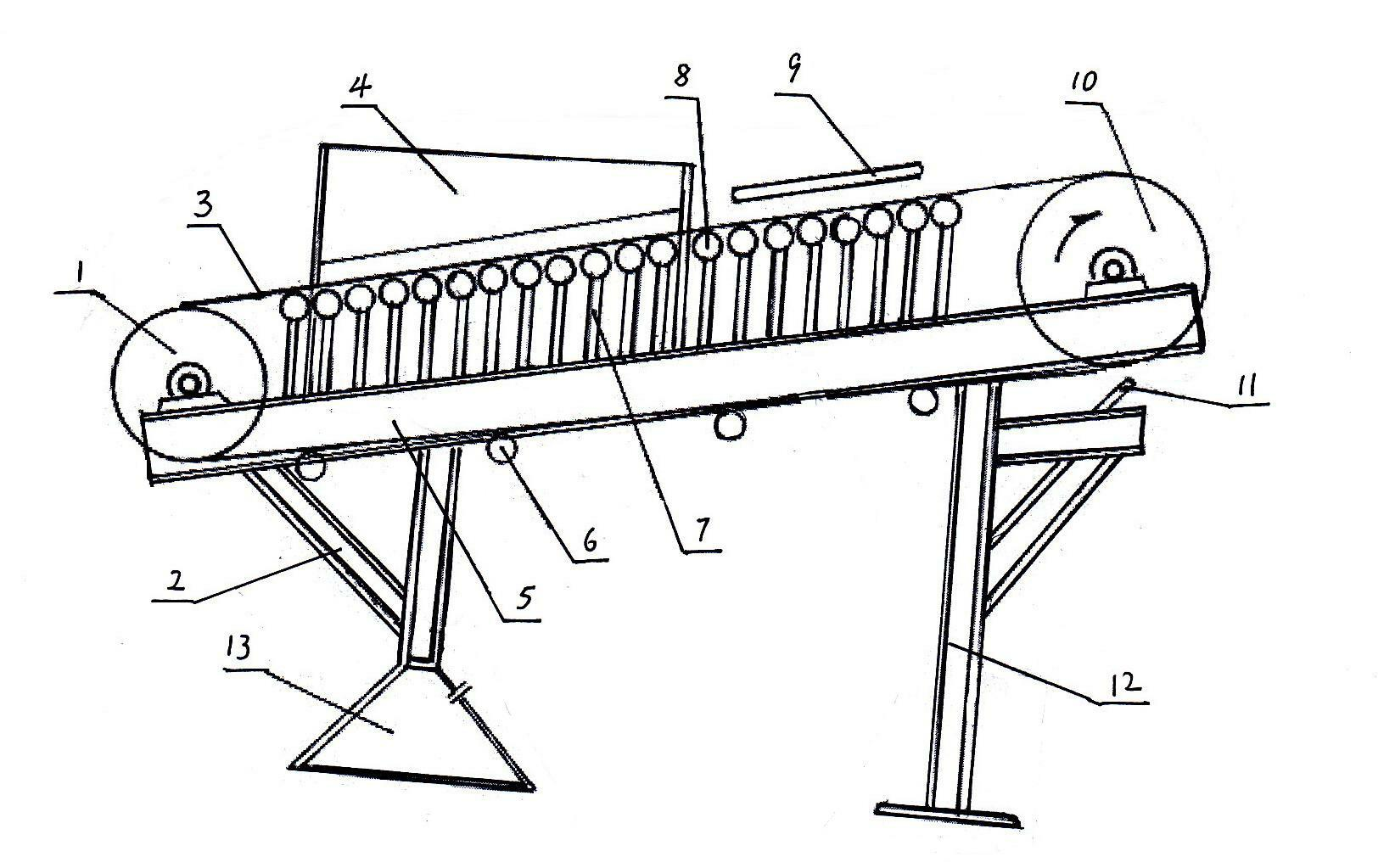
[0021] A belt-type roller magnetic separator, including a reversing drum 1, a left frame 2, a conveying belt 3, a rain step slurry dispersing screen 4, a belt conveying bracket 5, a conveying belt lower roller 6, and an upper washer 9 , the electric drum 10 and the right bracket 12, the conveyor belt 3 is wound on the reversing drum 1 and the electric drum 10, the left frame 2 and the right bracket 12 are respectively fixed under the left and right ends of the belt conveyor bracket 5, and the rain step slurry dispersion screen 4 and the upper washer 9 are respectively placed on the left end and the right end above the conveyor belt 3, and several groove-shaped high-strength magnet roller devices 8 are installed below the upper conveyor belt 3, and the high-strength magnet roller devices 8 are passed through Magnet support frame 7 is installed on the top of belt conveying support 5, idler roller 14 is formed on three separated conveyer belts, and permanent magnet 16 is housed in...

Embodiment 2

[0027] The structure of embodiment 2 is basically the same as embodiment 1, the difference is:

[0028] The high-strength magnet idler device 8 is made up of a grooved idler 17 and a grooved permanent magnet plate 18 on separate conveying belts, and a grooved permanent magnet is placed between two adjacent conveying belt grooved idlers 17. Magnet plate 18, groove-shaped permanent magnet plate 18 is installed on the top of belt conveying support 5 by magnet support frame 7.


PUM


Abstract

The invention discloses a belt type roller magnetic separator. The belt type roller magnetic separator comprises a redirecting roller, a left machine frame, a conveying belt, a rain spraying gradient slurry dispersing sieve, a belt conveying bracket, a conveying belt lower carrier roller, an upper flusher, an electric roller and a right bracket and is characterized in that: a plurality of groove-shaped high-strength magnet carrier roller devices are arranged below the conveying belt on the upper layer. The high-strength magnet carrier roller devices can magnetize patterned belts completely above the devices, and iron powder in the slurry is sucked by the magnetized patterned belts and falls into pits of the patterned belts. After the patterned belts upstream enters a non-magnetic region, all the iron concentrate powder falls into an iron concentrate powder bank and are collected, so that the magnetic separation efficiency is greatly improved. The belt type roller magnetic separator has the advantages of large conveying quantity, high collecting capacity, capacity of reducing washing of slurry on the adsorbed iron powder, high magnetic separation efficiency, high yield, high iron powder adsorption capacity, resource saving, simple structure and easiness in assembly, and is ideal equipment for extracting iron concentrate powder through iron ore magnetic separation and tailings treatment.

Description

technical field [0001] The invention relates to a magnetic separator, in particular to a belt roller magnetic separator used for mine wet magnetic separation and tailings recovery. Background technique [0002] At present, there are belt magnetic separators, drum magnetic separators, roller magnetic separators, disc magnetic separators, ring magnetic separators, cage magnetic separators and pulley magnetic separators in mining plants. All machines require multiple sets of processes for magnetic separation, which consumes a lot of power and the efficiency of magnetic separation is low. There will always be more iron powder flowing into the tailings storage, wasting a lot of precious limited resources. Contents of the invention [0003] The object of the present invention is to provide a belt-type roller magnetic separator with large conveying capacity, reduced erosion of the adsorbed iron powder by mud, high magnetic separation efficiency, high output, strong ability to ads...

Claims


Application Information

Patent Timeline
Patent Type & Authority Applications(China)
IPC IPC(8): B03C1/22B03B5/68
Inventor 周国发
Owner 周国发
Why Eureka
Try Eureka