Methods and systems for fuel vapor control

一种燃料蒸气、燃料系统的技术,应用在装料系统、燃料的热处理装置、燃料喷射装置等方向,能够解决燃料蒸气不充分冲洗、烃排放物增加、不充分冲洗等问题

Inactive Publication Date: 2013-08-14
FORD GLOBAL TECH LLC
View PDF9 Cites 1 Cited by
  • Summary
  • Abstract
  • Description
  • Claims
  • Application Information

AI Technical Summary

Problems solved by technology

However, shorter engine run times combined with low intake manifold vacuum may result in insufficient flushing of fuel vapors from the fuel vapor canister connected between the intake manifold and fuel tank
Also, under conditions such as warmer ambient temperatures, when fuel vapor generation in the fuel tank increases, insufficient flushing of the fuel vapor canister results in increased hydrocarbon emissions to the atmosphere

Method used


Image

  • Methods and systems for fuel vapor control
  • Methods and systems for fuel vapor control
  • Methods and systems for fuel vapor control

Examples


Embodiment Construction

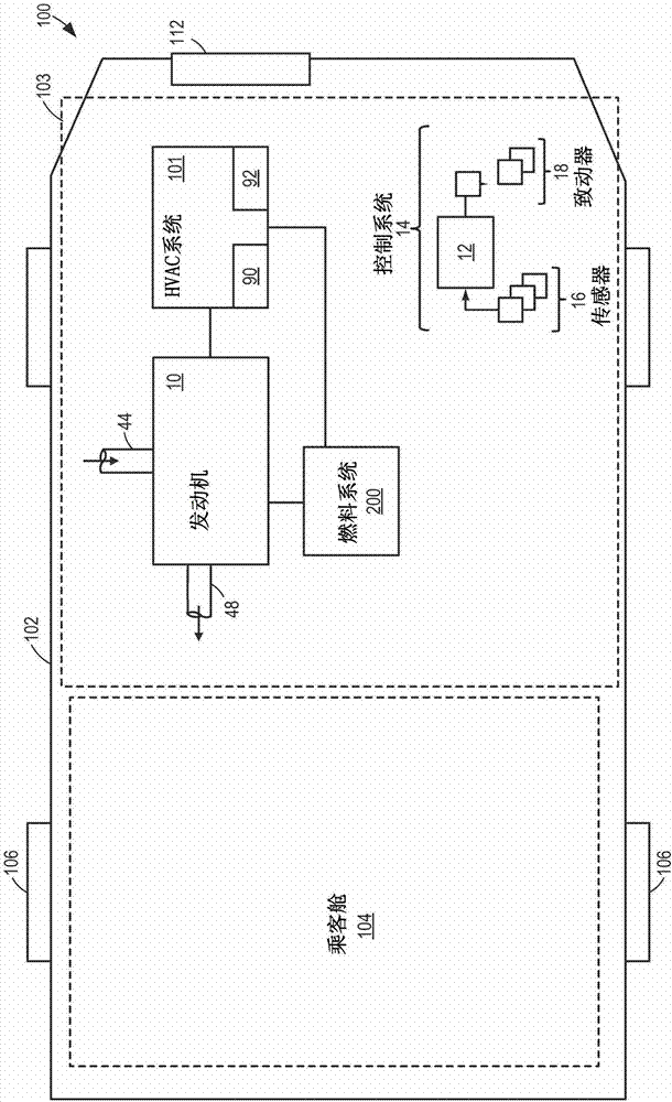
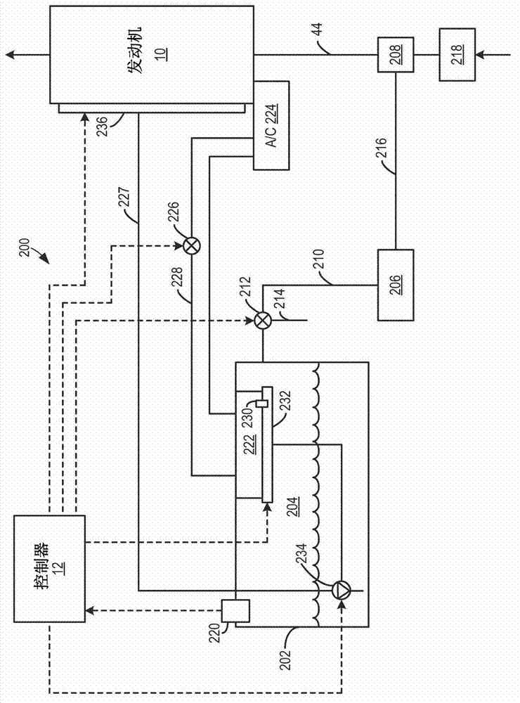
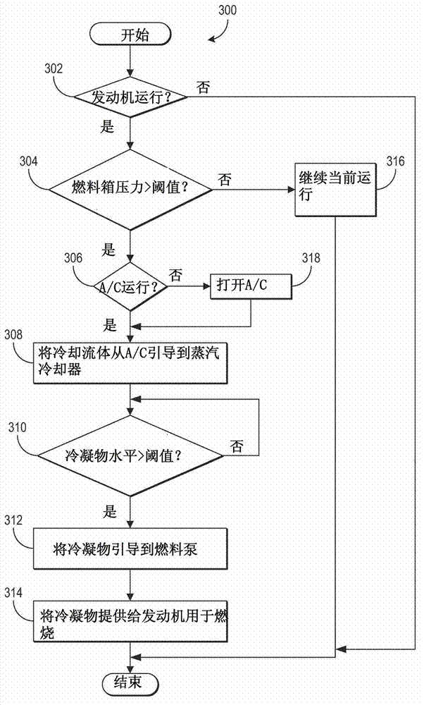
[0022] The following description relates to various embodiments of methods and systems for controlling the pressure in a fuel tank. In an example, a method for a fuel system includes, in response to operating conditions, condensing fuel vapor in an oil vapor cooler provided in the fuel tank, and delivering the condensed fuel vapor to a fuel pump or the fuel The pressurized fuel line between the pump and the nozzle. For example, the vapor cooler may be fluidly connected to the cooling system so that heat exchange can occur between the fuel vapor in the fuel tank and the cooling fluid circulating through the vapor cooler. In this way, the fuel vapor in the fuel tank can be condensed, so that, for example, at a relatively high ambient temperature, the pressure in the fuel tank can be reduced when the pressure of the fuel tank is high. Moreover, in another embodiment, the cooling system operation can be adjusted according to the fuel tank. Various examples will be described in de...


PUM


Abstract

Various methods and systems are provided for reducing pressure in a fuel tank of a fuel system of an engine. In one example, cooling fluid is routed from an air conditioner of a cooling system to a vapor cooler disposed in a vapor space of the fuel tank such that fuel vapor in the fuel tank may be condensed and routed to a fuel pump for delivery to the engine, thereby reducing a fuel tank pressure.

Description

Technical field [0001] The present invention relates to pressure control in a fuel tank in a vehicle such as a hybrid vehicle. Background technique [0002] Reducing engine operating time in hybrid vehicles can realize the benefits of fuel economy and reduced regulated emissions. However, the shorter engine operating time combined with the low intake manifold vacuum may cause insufficient flushing of fuel vapor from the fuel vapor canister connected between the intake manifold and the fuel tank. Furthermore, under conditions such as relatively warm ambient temperatures, when the production of fuel vapor in the fuel tank increases, insufficient flushing of the fuel vapor canister results in an increase in hydrocarbon emissions to the atmosphere. Summary of the invention [0003] The inventor herein recognized the above problem and invented a method to at least partially solve this problem. In one example, a method for a fuel system is provided. The method includes, in response t...

Claims


Application Information

Patent Timeline
Patent Type & Authority Applications(China)
IPC IPC(8): F02M25/08
CPCF02M31/20F02M2025/0863Y02T10/126F02M25/08Y02T10/12
Inventor N·C·克拉格
Owner FORD GLOBAL TECH LLC
Why Eureka
Try Eureka