Method and device for thermo chemolysis of CO2 and H2O based on reaction substance circulation
A technology of reaction device and reaction substance, which is applied in chemical instruments and methods, separation methods, and separation of dispersed particles, etc., can solve the problems of high decomposition temperature of metal oxides, achieve easy large-scale industrial application, appropriate reaction temperature, and reduce negative effects Effect
- Summary
- Abstract
- Description
- Claims
- Application Information
AI Technical Summary
Problems solved by technology
Method used
Image


Examples
specific Embodiment 1
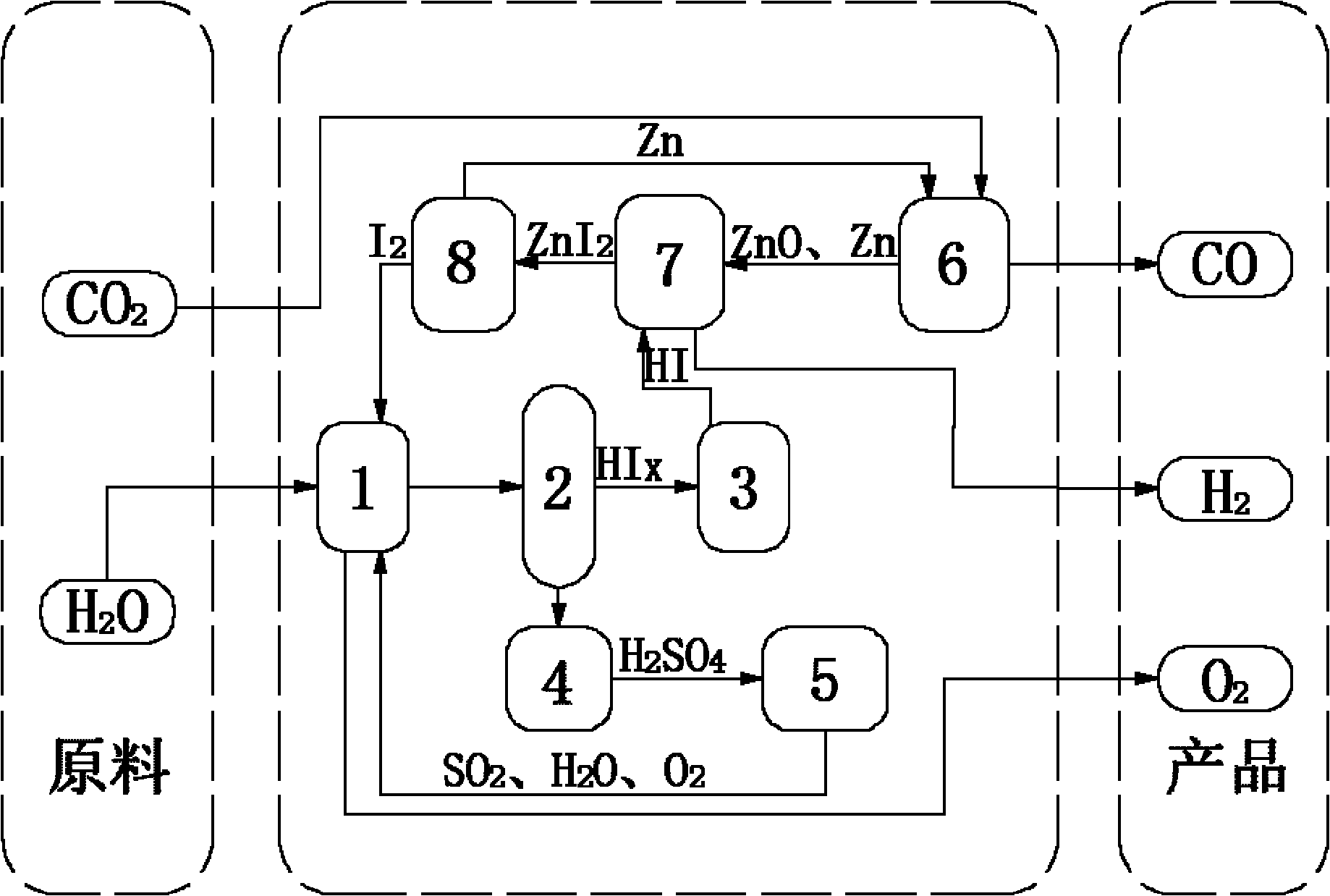
[0043] (1) 14molH 2 O, 1.5molI 2 and 1molSO 2 Send it into the Bunsen reaction device 1, stir the reaction solution at a constant speed by the motor device to ensure that it is evenly mixed, and an autonomous exothermic reaction occurs at 20 ° C and 1 atm to produce a watery HI phase (HI x ) and H 2 SO 4 Phase solution, in which the HI phase mainly contains hydrogen iodide solution and excess iodine, H 2 SO 4 Phase mainly contains H 2 SO 4 Solution, the chemical reaction formula of this reaction is as follows:
[0044] I 2 +SO 2 +2H 2 O→2HI+H 2 SO 4
[0045] (2) the two solutions in the Bunsen reaction unit 1 are separated in the liquid phase separation unit 2, H 2 SO 4 Phase in H 2 SO 4 After being concentrated in the concentration device 4, it enters the concentrated H 2 SO 4 In the catalytic decomposition device 5, it is first decomposed into SO at 350°C 3 and H 2 O, generated SO 3 Catalytic decomposition at 800°C to generate SO 2 and O 2 , the final...
specific Embodiment 2
[0053] (1) 15molH 2 O, 5molI 2 and 1molSO 2 Send it into the Bunsen reaction device 1, stir the reaction solution at a constant speed by the motor device to ensure that it is evenly mixed, and an autonomous exothermic reaction occurs at 70 ° C and 1.5 atm, producing a HI phase with more water (HI x ) and H 2 SO 4 Phase solution, in which the HI phase mainly contains hydrogen iodide solution and excess iodine, H 2 SO 4 Phase mainly contains H 2 SO 4 Solution, the chemical reaction formula of this reaction is as follows:
[0054] I 2 +SO 2 +2H 2 O→2HI+H 2 SO 4
[0055] (2) the two solutions in the Bunsen reaction unit 1 are separated in the liquid phase separation unit 2, H 2 SO 4 Phase in H 2 SO 4 After being concentrated in the concentration device 4, it enters the concentrated H 2 SO 4 In the catalytic decomposition device 5, it is first decomposed into SO at 350°C 3 and H 2 O, generated SO 3 Catalytic decomposition at 850°C to generate SO 2 and O 2 , ...
specific Embodiment 3
[0063] (1) 16molH 2 O, 9molI 2 and 1molSO 2 Send it into the Bunsen reaction device 1, stir the reaction solution at a constant speed by the motor device to ensure that it is evenly mixed, and an autonomous exothermic reaction occurs at 120 ° C and 2 atm to produce a watery HI phase (HI x ) and H 2 SO 4 Phase solution, in which the HI phase mainly contains hydrogen iodide solution and excess iodine, H 2 SO 4 Phase mainly contains H 2 SO 4 Solution, the chemical reaction formula of this reaction is as follows:
[0064] I 2 +SO 2 +2H 2 O→2HI+H 2 SO 4
[0065] (2) the two solutions in the Bunsen reaction unit 1 are separated in the liquid phase separation unit 2, H 2 SO 4 Phase in H 2 SO 4 After being concentrated in the concentration device 4, it enters the concentrated H 2 SO 4 In the catalytic decomposition device 5, it is first decomposed into SO at 350°C 3 and H 2 O, generated SO 3 Catalytic decomposition at 900°C to generate SO 2 and O 2 , the final ...
PUM
 Abstract
Description
Claims
Application Information
 - R&D
- Intellectual Property
- Life Sciences
- Materials
- Tech Scout
- Unparalleled Data Quality
- Higher Quality Content
- 60% Fewer Hallucinations
Browse by: Latest US Patents, China's latest patents, Technical Efficacy Thesaurus, Application Domain, Technology Topic, Popular Technical Reports.
© 2025 PatSnap. All rights reserved.Legal|Privacy policy|Modern Slavery Act Transparency Statement|Sitemap|About US| Contact US: help@patsnap.com