Method for clamping a tool or a workpiece and device for performing the method

A technology for clamping tools and fixtures, applied in metal processing machine parts, manufacturing tools, metal processing, etc., can solve problems such as high inaccuracy, inaccurate simulated length measurement, etc., and achieve the effect of simplifying the structure

Inactive Publication Date: 2012-07-04
ROHM CO LTD
View PDF8 Cites 2 Cited by
  • Summary
  • Abstract
  • Description
  • Claims
  • Application Information

AI Technical Summary

Problems solved by technology

The practical application of the electric gripper disclosed in DE 10 2006 015 918 A1 has already given the aspect to be improved with regard to stroke control, since the analog length measurement by the sensors used is relatively inaccurate
Furthermore, it is problematic to make full use of the motor torque in order to control the clamping force achieved, which likewise involves relatively high inaccuracies

Method used


Image

  • Method for clamping a tool or a workpiece and device for performing the method
  • Method for clamping a tool or a workpiece and device for performing the method
  • Method for clamping a tool or a workpiece and device for performing the method

Examples


Embodiment Construction

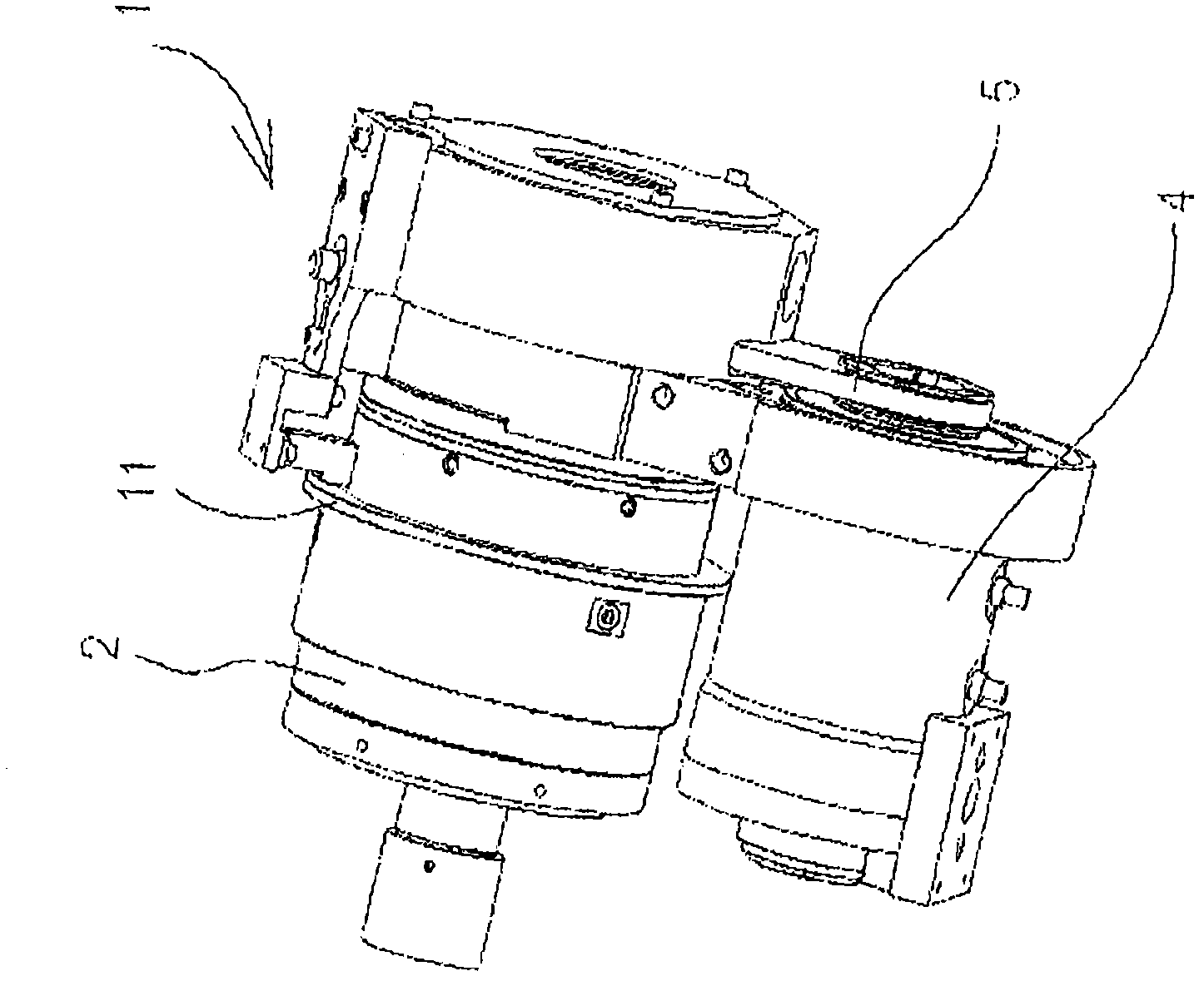
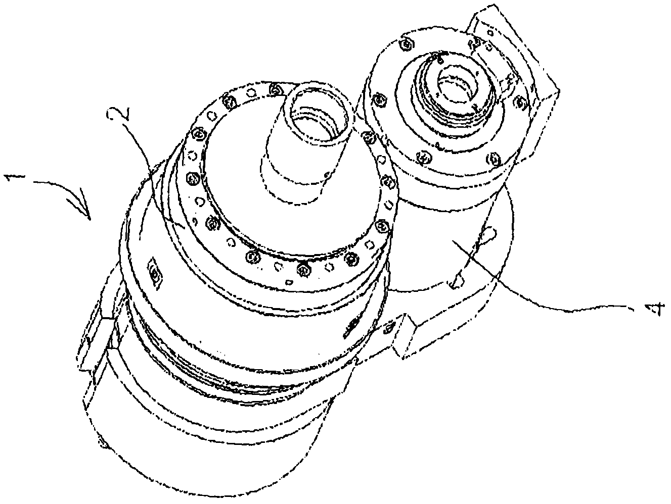
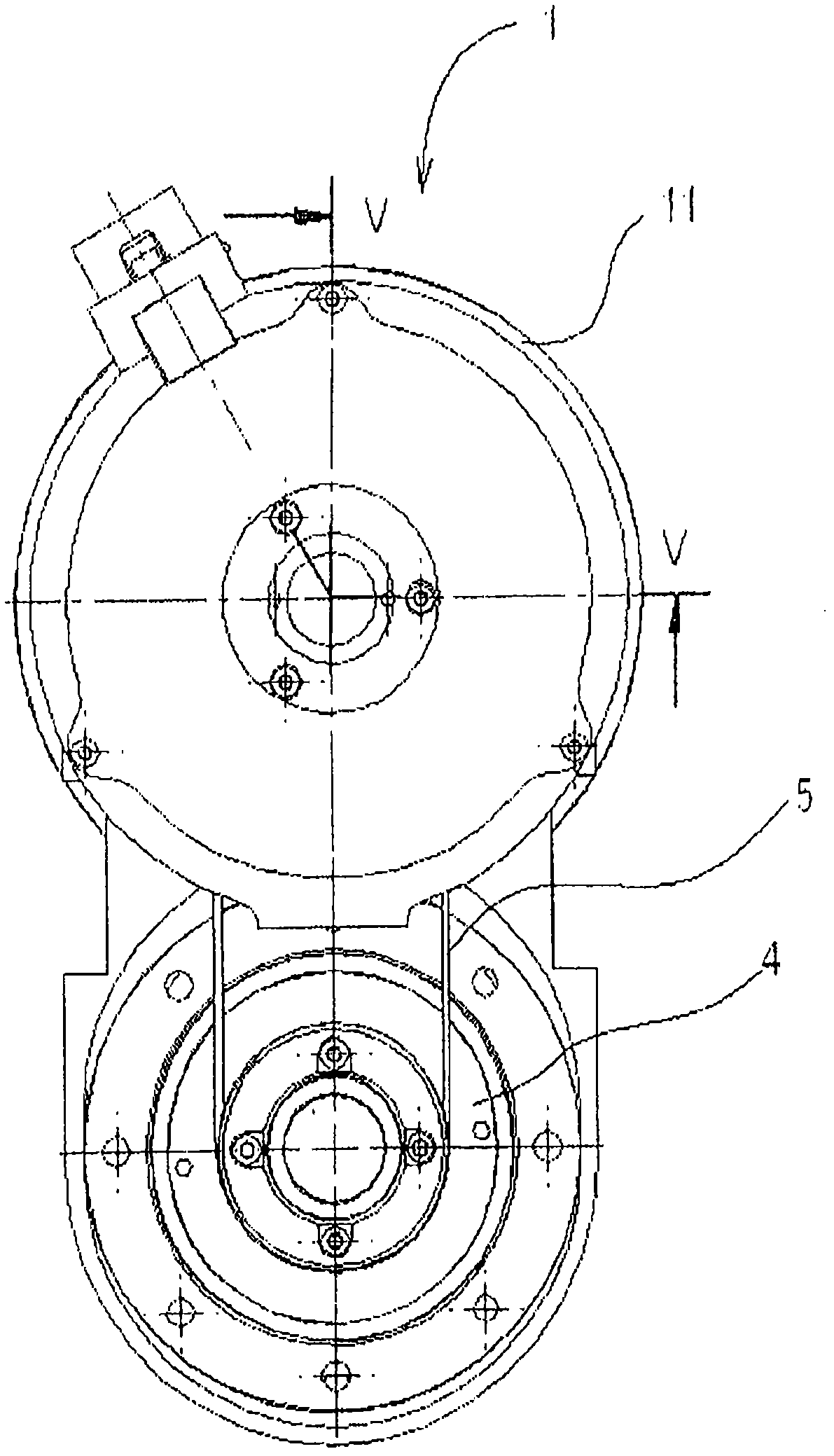
[0020] The drawing shows an electric clamping clamp 1 , which serves to adjust the jaws of a chuck fixed to a machine tool and clamps it continuously and securely relative to a workpiece or tool during the clamping process. The electric clamp 1 has a housing 2 to be fixed on the working spindle of the machine tool, in which a threaded rod 3 is axially adjustable for adjusting the jaws of the chuck. The electric gripper 1 also includes an electric servomotor 4 which is arranged laterally next to the housing 2 . As the transmission between the electric servo motor 4 and the screw 3, a harmonic drive is used, wherein the rotor of the servo motor 4 is connected to the drive wheel 6 through a belt drive 5, and the drive wheel is connected to the coaxial exciter of the harmonic drive. The hollow wheel of the harmonic drive is connected with the housing 2, and the flexible spine (Flex-Spine) of the harmonic drive acts as the drive of the screw 3. In the embodiment shown in the drawi...


PUM


Abstract

The invention relates to a method for clamping a tool or a workpiece by means of an electric clamp (1), which comprises a housing (2), which is fastened to the working spindle of a machine tool and in which a threaded rod (3) for adjusting the clamping jaws of a chuck is supported in an axially adjustable manner, and an electric servomotor (4), the rotor of which is in a driving connection with a drive wheel (6) that adjusts the spindle nut (7) of the threaded rod (3), wherein a first sensor for detecting the axial position of the threaded rod is associated with the threaded rod (3) and a second sensor for detecting the axial position of the spindle nut is associated with the spindle nut (7), comprising the method step of determining the position of the threaded rod (3) by means of the first sensor while a slight axial force occurs as a result of the contact of the clamping jaws against the tool or the workpiece and continued adjustment of the spindle nut (7) until a specified pick-up difference (12) between the first sensor and the second sensor is detected by means of the second sensor. The invention further relates to a device for performing the method.

Description

technical field [0001] The invention relates to a method for clamping a tool or workpiece with an electric clamp comprising a housing fixed to the working spindle of a machine tool, in which a screw is axially adjustable for adjusting the jaws of a chuck, and also It consists of an electric servo motor whose rotor is in driving connection with the drive wheel of the nut of the adjusting screw, wherein a first sensor for detecting the axial position of the screw is attached to the screw, and a second sensor for detecting the axial position of the nut is attached to the nut. Two sensors, the method comprises the method steps of determining the position of the screw by means of a first sensor when a slight axial force is generated due to the abutment of the jaws against the tool or workpiece, and continuously adjusting the nut until the position of the screw is determined by means of the second sensor. A given sensor difference from the second sensor. The subject of the inventio...

Claims


Application Information

Patent Timeline
Patent Type & Authority Applications(China)
IPC IPC(8): B23B31/28B23Q17/00
CPCB23B2260/128B23B2260/062B23B31/28Y10T409/30952Y10T29/49771Y10T279/275Y10T29/53087Y10T29/4978Y10T29/49998Y10T279/21B23B2260/136B23Q17/003E05B77/06E05B79/20E05B85/16B23Q16/00B23Q17/00
Inventor E·杭莱特P·申克
Owner ROHM CO LTD
Why Eureka
Try Eureka