
Radio frequency (RF) communication device and control method, remote controller, controlled device and household appliance

A technology of radio frequency communication and transmitting device, applied in the fields of radio frequency communication device and control method, controlled equipment and household appliances, remote control, can solve the problems of increasing power consumption, increasing chip power consumption, increasing the burden of central processing unit, etc. Achieve the effect of reducing power consumption, reducing burden, and avoiding cross transmission

Active Publication Date: 2014-06-04
MIDEA GRP CO LTD
View PDF2 Cites 0 Cited by
  • Summary
  • Abstract
  • Description
  • Claims
  • Application Information

AI Technical Summary

Problems solved by technology

[0004] The above-mentioned control has the following deficiencies: the existing radio frequency home appliances need to fix an ID or address when leaving the factory, so the production process of the same kind of radio frequency equipment must be added to write different IDs or addresses into each radio frequency device respectively; the existing radio frequency home appliances When devices communicate, RF communication data packets will be cross-transmitted. When similar devices are adjacent to each other, they will easily receive invalid RF data packets. Since the validity of the data packets needs to be judged by the central processing unit, the burden on the central processing unit will be increased. , especially when low-power devices (such as remote controls) will frequently switch from sleep to working state, which increases the power consumption of the chip; because the distance between the communication parties of radio frequency home appliances is sometimes long (such as wall-mounted air conditioners and remote controls), When performing the pairing operation of existing radio frequency home appliances, since the target pairing device does not limit the pairing operation time limit, when the position of the pairing initiator device (such as a radio frequency remote control) is fixed, if the pairing initiator device and the target pairing device (such as a radio frequency air conditioner) is less than the distance between the pairing initiating device and another non-target pairing device that is the same as the target pairing device, the pairing initiating device will not be able to establish a pairing relationship with the target pairing device, and will mistakenly connect with the closer non-target pairing device Establish a pairing relationship
[0005] The reasons for the above shortcomings are: RF home appliances do not have automatic ID or address generators, so only one ID or address can be fixed at the factory for each RF device; when the same type of RF device communicates, it does not filter non-self RF data in the RF data transceiver module The mechanism causes the RF data packets of the same type of RF devices to be cross-received, which increases the burden on the central processing unit, reduces the sleep time of low-power RF devices (such as RF remote controls), and increases power consumption; When the radio frequency devices are adjacent, the pairing target device has no limit and the time limit for pairing operation is easy to cause pairing between the pairing initiator device and the non-target pairing device

Method used

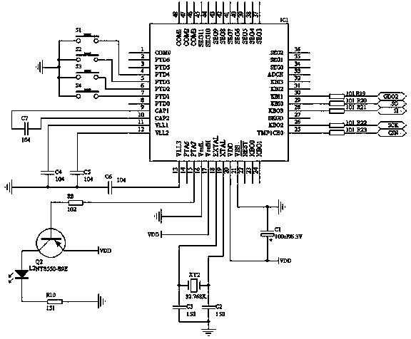
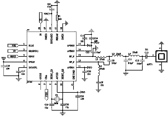

Image

  • Radio frequency (RF) communication device and control method, remote controller, controlled device and household appliance
  • Radio frequency (RF) communication device and control method, remote controller, controlled device and household appliance
  • Radio frequency (RF) communication device and control method, remote controller, controlled device and household appliance

Examples


Embodiment Construction

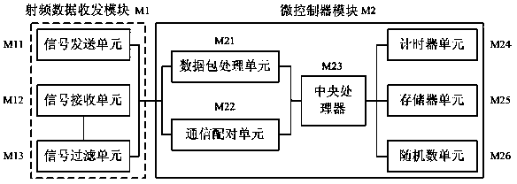
[0068] figure 1 It is a structural block diagram of the radio frequency communication device of the present invention. The radio frequency communication device is composed of a data transceiver module M1 and a microcontroller module M2. The data transceiving module M1 includes: a signal sending unit M11, a signal receiving unit M12 and a signal filtering unit M13. The signal receiving unit M12 is connected to the signal filtering unit M13, and the signal filtering unit M13 and the signal sending unit are simultaneously connected to the microcontroller module M2. The microcontroller module M2 includes: a data packet processing unit M21, a communication pairing unit M22, a central processing unit M23, a timer unit M24, a memory unit M25 and a random number unit M26. The central processing unit M23 is the control core of the microcontroller module M2. The microcontroller module M2 is connected to the central processing unit M23 except for the central processing unit M23. The da...


PUM


Abstract

The invention provides a radio frequency (RF) communication device and a control method, a remote controller, a controlled device and a household appliance. The RF communication device comprises a micro-controller module and an RF data transceiver module; the RF data transceiver module is used for transceiving the communication data packet and paired data packet of the micro-controller module; the RF data transceiver module comprises a signal transmitting unit, a signal receiving unit and a signal filtering unit; the signal receiving unit is connected with the signal filtering unit; the signal filtering unit and the signal transmitting unit are connected with the micro-controller module; the micro-controller module comprises a central processor and a data packet processing unit, a communication paired unit, a random number unit and a memory cell that are connected with the central processor; and the data packet processing unit and the communication paired unit are connected between the central processor and the RF data transceiver module. According to the device, the production process of the RF device is simplified, the cross-transmission of similar RF device data packets is reduced, the burden of the central processor is eased, and the power consumption of the low-power consumption device is also reduced.

Description

technical field [0001] The present invention relates to the field of communication involving household appliances, and more precisely relates to a radio frequency communication device and a control method, a remote controller, controlled equipment and household appliances. Background technique [0002] The radio frequency remote control has no directional restrictions on control, that is, it can be effectively controlled without facing the controlled device, and can be controlled through certain obstacles (transparent or opaque obstacles may exist between the remote control and the controlled device), and the effective control distance is long. , fast information transmission speed and easy two-way data transmission (that is, the data between the remote control and the controlled device can be transmitted to each other) are adopted by more and more home appliance manufacturers. [0003] In order to prevent crosstalk between home appliances using the same radio frequency ...

Claims


Application Information

Patent Timeline
Patent Type & Authority Patents(China)
IPC IPC(8): G08C17/02
CPCY02B60/50
Inventor 莫中勇付新王丽娜
Owner MIDEA GRP CO LTD
Learn More