
Scanning method for non-boundary scanning device

A non-boundary and device-based technology, applied in the field of integrated circuit board-level production and testing, can solve problems such as difficult and complex logic description, weak circuit board logic expression description, etc., and achieve the effect of easy recognition and understanding, and simple description

Inactive Publication Date: 2012-07-04
苏州工业园区谱芯科技有限公司
View PDF0 Cites 5 Cited by
  • Summary
  • Abstract
  • Description
  • Claims
  • Application Information

AI Technical Summary

Problems solved by technology

[0008] The IBIS model is a fast and accurate modeling method for I / O BUFFER based on the V / I (voltage / current) curve. It is an international standard that reflects the electrical characteristics of the chip driver and receiver. It provides a standard file format to Record parameters such as drive source output impedance, rise / fall time, and input load, which is very suitable for calculation and simulation of high-frequency effects such as oscillation and crosstalk. However, the description of the logic expression required for circuit board testing is weak
[0009] The cluster model is a language developed by American Asset Company to describe non-scanning devices. It can complete the description of simple logic, such as exclusion, AND gate, and NOT gate, but it is difficult to complete the description of complex logic.

Method used


Image

  • Scanning method for non-boundary scanning device
  • Scanning method for non-boundary scanning device
  • Scanning method for non-boundary scanning device

Examples


Embodiment Construction

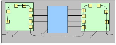
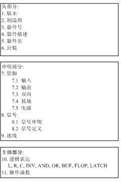
[0028] Please refer to figure 1 As shown, the present invention discloses a description method of a non-boundary scan device, which splits the description of a non-boundary scan device into a header part, a declaration part and a main part. The three parts are described in detail below:

[0029] header part:

[0030]The description format of the header part includes: keywords, numbers or character strings, and ending symbols. The header part includes a description of the version of the non-boundary scan device, a description of the manufacturer of the non-boundary scan device, a description of the part number of the non-boundary scan device, a description of the device information of the non-boundary scan device, a description of the non-boundary scan device A description of the device name of the boundary-scan device, and a description of the package of the non-boundary-scan device.

[0031] 1. version

[0032] Description format: VERSION number ending symbol

[0033] No...


PUM


Abstract

The invention discloses a scanning method for a non-boundary scanning device. The description of the non-boundary scanning device is divided into a head section, a declaration section and a main body section, wherein the description format of the head section comprises keywords, numbers or character strings and an end symbol; the declaration section comprises a pin description, a signal description and a connection wire description; a pin is used for describing encapsulation of the non-boundary scanning device; a signal is used for describing a relation between a logic signal of the non-boundary scanning device and the pin; and the description format of the main body section comprises a left expression, operators and a right expression. The scanning method has the beneficial effects that: the description of the non-boundary scanning device is divided into three sections, so that the description is simple, and can be identified and understood by a computer easily; and furthermore, a complicated logic can be described by performing various permutations and combinations on the operators.

Description

technical field [0001] The invention relates to a description method of a non-boundary scan device, which belongs to the field of integrated circuit board-level production testing. Background technique [0002] With the development of integrated circuits into the era of VLSI, the high complexity of circuit boards and multi-layer printed boards, surface mount (SMT), ball grid array (BGA), wafer scale integration (WSI) and multi-chip modules The application of (MCM) technology in the circuit system has made the physical accessibility of circuit nodes gradually weakened or even disappeared, and the testability of circuits and systems has declined sharply. Due to the increasing integration of circuit boards, the distance between nodes available for testing is getting smaller and smaller, and some even completely become recessive nodes. In this case, if only traditional testing methods such as probes and needle beds There are many disadvantages in the device failure test of the ...

Claims


Application Information

Patent Timeline
IPC IPC(8): G01R31/28G01R31/317
Inventor 胡国兴
Owner 苏州工业园区谱芯科技有限公司
Learn More