


Quick Research
Generate reliable direction feasibility study reports for your R&D in just a few steps.

Technical Q&A
Discover and master advanced knowledge NOW. Basics, ideas, possibilities, all at once.

Find Solutions
As an expert in R&D theories, this can generate solutions to your technical problems instantly.

Evaluate Feasibility
Analyze your overall solution with one click, know your potential R&D risks in advance.

Monitor Landscape
Get weekly tech updates, stay abreast of the latest tech innovations and key insights.
Hydraulic control system for scooptram
A technology of hydraulic control system and scraper, which is applied in the direction of earth mover/shovel, construction, etc., can solve the problems that the scraper cannot start and turn quickly at the same time, and uses few components, and achieves a simple structure and uses components. Fewer, reliable results
- Summary
- Abstract
- Description
- Claims
- Application Information
AI Technical Summary
Problems solved by technology
Method used
Image

Examples
Embodiment approach 1
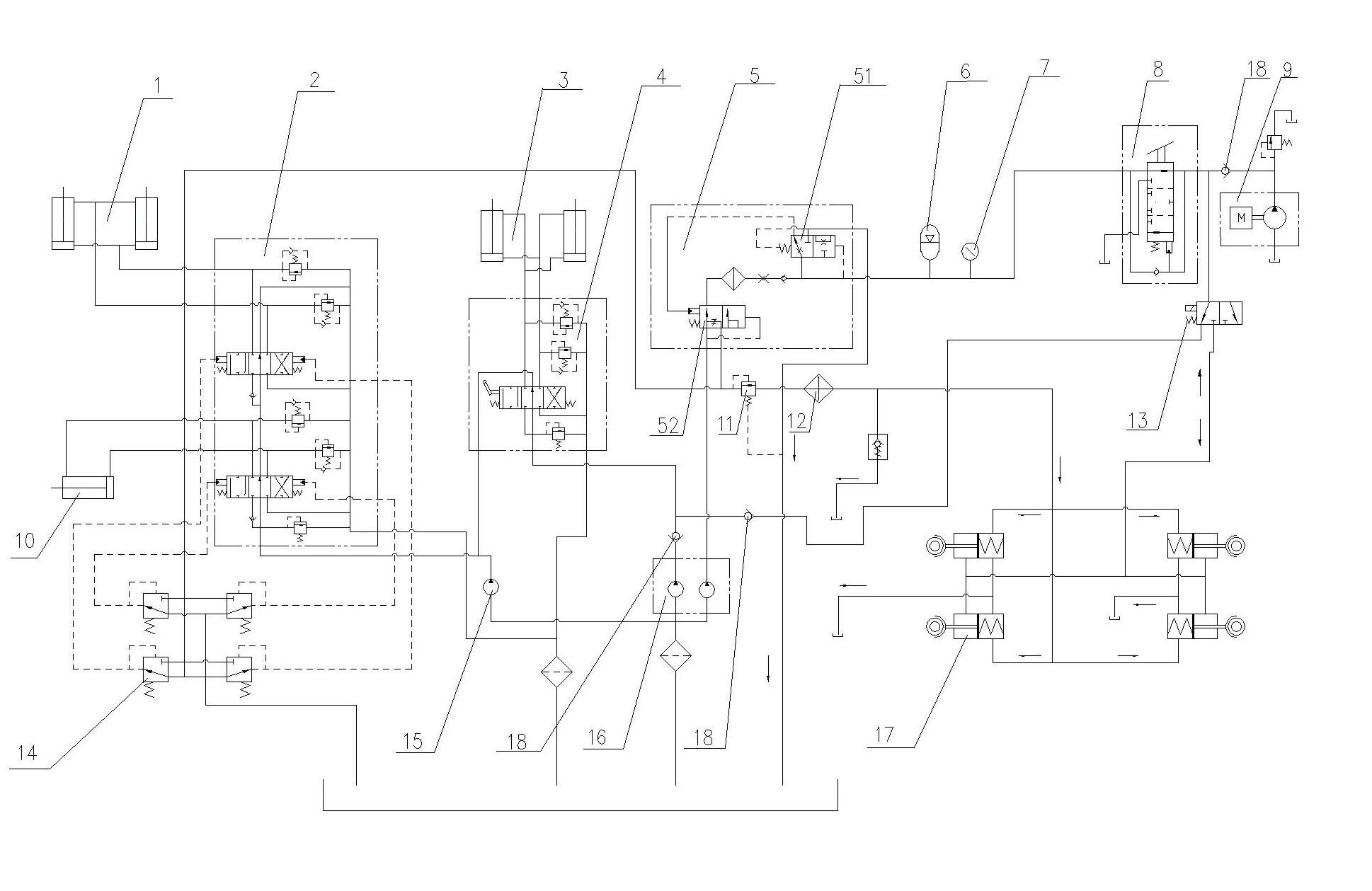
[0012] Embodiment 1, see figure 1 :
[0013] From figure 1 It can be seen that the right pump of the dual gear pump 16 is used for the oil supply of the brake circuit, and the left pump is used for the oil supply of the steering circuit. Valve 5, foot brake valve 8, electromagnetic reversing valve 13, brake 17, double gear pump 16, the right pump is directly connected to the input end of filling valve 5, the backup oil supply branch and the input end of electromagnetic reversing valve 13 Both are connected to the output end of the foot brake valve 8, one of the two output ports of the electromagnetic reversing valve 13 is connected to the brake 17, and the other is connected to the input end of the steering control valve 4 through the reverse check valve 18. When the system works normally, the electric hydraulic pump 9 does not start, which will not interfere with the normal work of the hydraulic system. The left pump of the dual gear pump 16 supplies oil to the steeri...
Embodiment approach 2
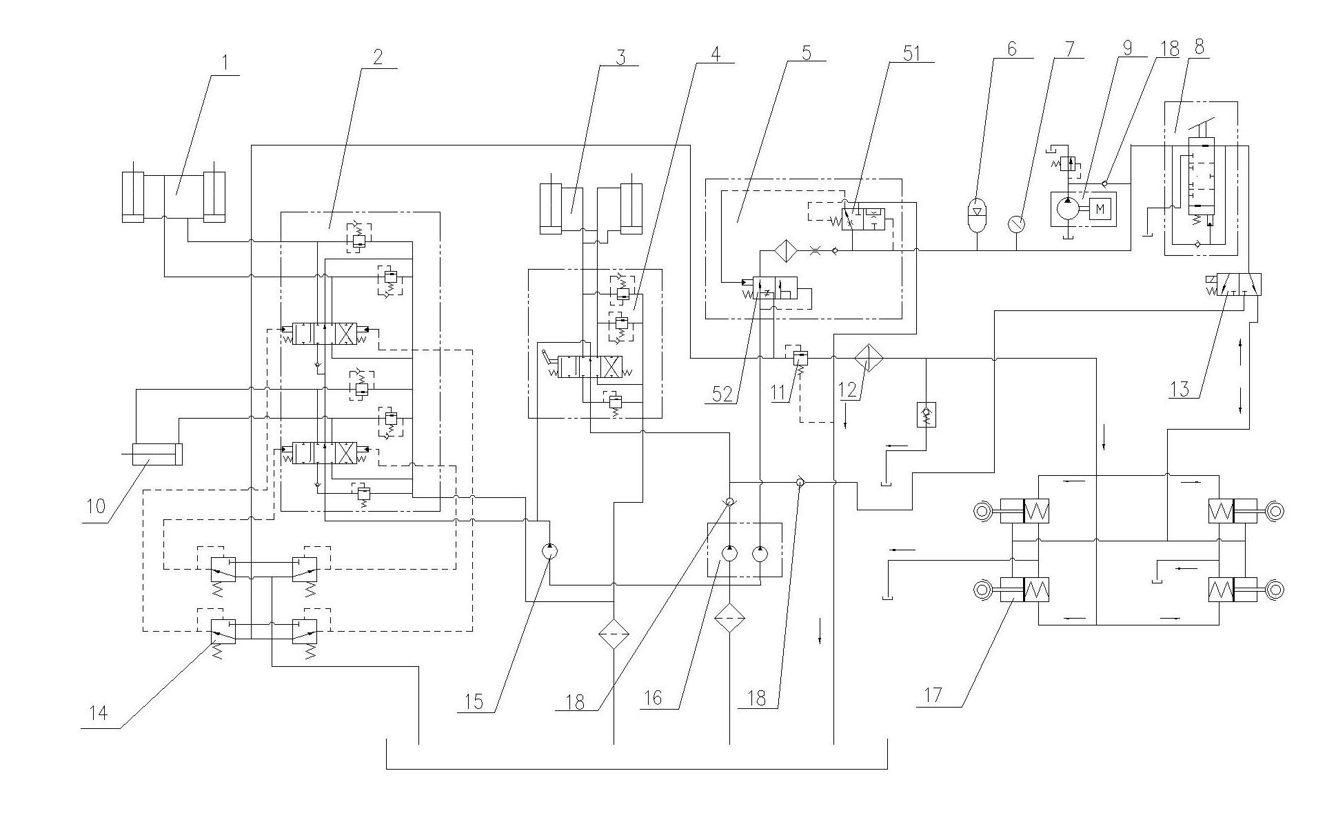
[0015] Implementation mode two, see figure 2 :
[0016] From figure 2 It can be seen that this embodiment is compared with the above-mentioned embodiment, the double gear pump 16 right pump of this embodiment is directly connected to the input end of the filling valve 5, and the backup oil supply branch is connected to the input end of the foot brake valve 8, and the electromagnetic One of the two output interfaces of the reversing valve 13 is connected to the brake 17 , and the other is connected to the input end of the steering control valve 4 through the reverse check valve 18 . ( figure 2 )
Embodiment approach 3
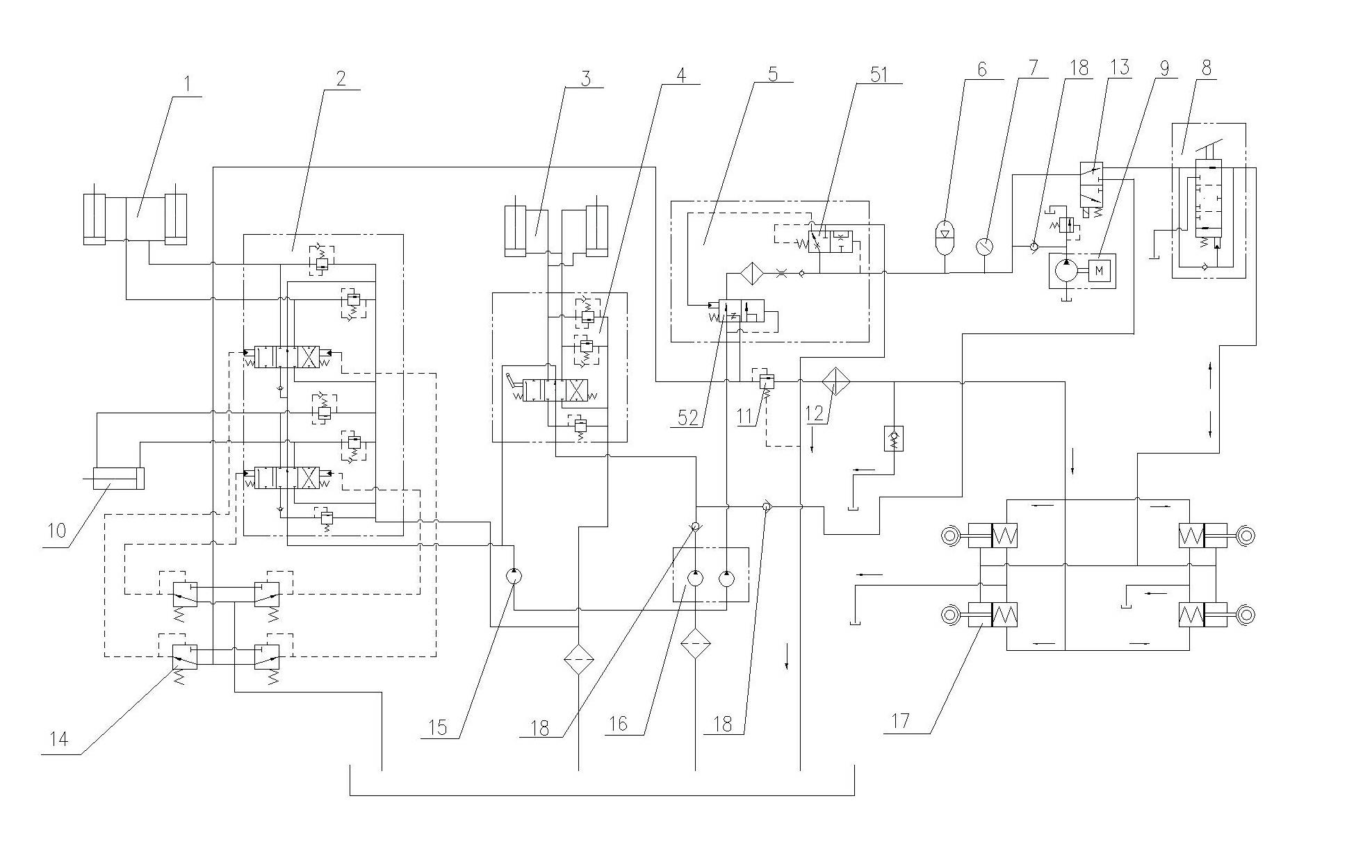
[0017] Implementation mode three, see image 3 :
[0018] Compared with Embodiment 1, the right pump of the double gear pump 16 in this embodiment is directly connected to the input end of the filling valve 5, and the backup oil supply branch and the input end of the electromagnetic reversing valve 13 are connected to the output end of the accumulator 6. One of the two output interfaces of the electromagnetic reversing valve 13 is the input end of the foot brake valve 8, and the other is connected to the input end of the steering control valve 4 through the reverse check valve 18. ( image 3 )
PUM
 Abstract
Description
Claims
Application Information
 - R&D Engineer
- R&D Manager
- IP Professional
- Industry Leading Data Capabilities
- Powerful AI technology
- Patent DNA Extraction
Browse by: Latest US Patents, China's latest patents, Technical Efficacy Thesaurus, Application Domain, Technology Topic, Popular Technical Reports.
© 2024 PatSnap. All rights reserved.Legal|Privacy policy|Modern Slavery Act Transparency Statement|Sitemap|About US| Contact US: help@patsnap.com