
Suction cup clamping device

A clamping device and suction cup technology, applied in welding equipment, laser welding equipment, metal processing equipment, etc., can solve the problems of affecting processing accuracy, damage to film materials, and difficulty in ensuring processing accuracy, so as to improve processing accuracy and ensure suction Balance and ensure the effect of machining accuracy

Inactive Publication Date: 2015-08-19
BEIJING UNIV OF TECH
View PDF5 Cites 0 Cited by
  • Summary
  • Abstract
  • Description
  • Claims
  • Application Information

AI Technical Summary

Problems solved by technology

When using a pressing plate to fix the film, there will be the following problems: the film material is easily deformed, and the processing difficulty increases, which affects the processing accuracy; low efficiency
[0004] In addition, when processing miniaturized film materials, it is impossible to clamp and fix the miniaturized film materials with a press plate
Although the miniaturized film material can be fixed by adhesive, it may damage the surface of the film material
Sometimes it is also possible to use a suction device to absorb and fix the film material, but this method cannot guarantee the flatness of the film material, which in turn affects the accuracy of laser processing
[0005] In addition, when using a laser to process thin film materials, after the laser etches the thin film material, if it does not pass through smoothly, it will accumulate on the bottom surface of the thin film material, which will affect the processing accuracy.
[0006] Therefore, it is necessary to further improve the clamping device of the pressing plate used in the above-mentioned laser processing film material, so as to avoid the easy deformation of the film material, the difficulty of processing, the difficulty in ensuring the processing accuracy, the damage of the film material, and the waste of the film material in the above-mentioned clamping device. Defects such as resources and cumbersome processing

Method used


Image

  • Suction cup clamping device
  • Suction cup clamping device
  • Suction cup clamping device

Examples


Embodiment Construction

[0019] Below, the present invention will be described in further detail in conjunction with the accompanying drawings and specific embodiments.

[0020] In the following description, some exemplary embodiments of the present invention are described by way of illustration only, and those of ordinary skill in the art will recognize that, without departing from the spirit and scope of the present invention, the The described embodiments can be modified in various ways. Accordingly, the drawings and description are merely illustrative in nature and are not intended to limit the scope of the claims. In addition, in this specification, the same code|symbol represents the same part.

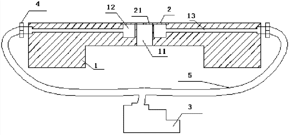
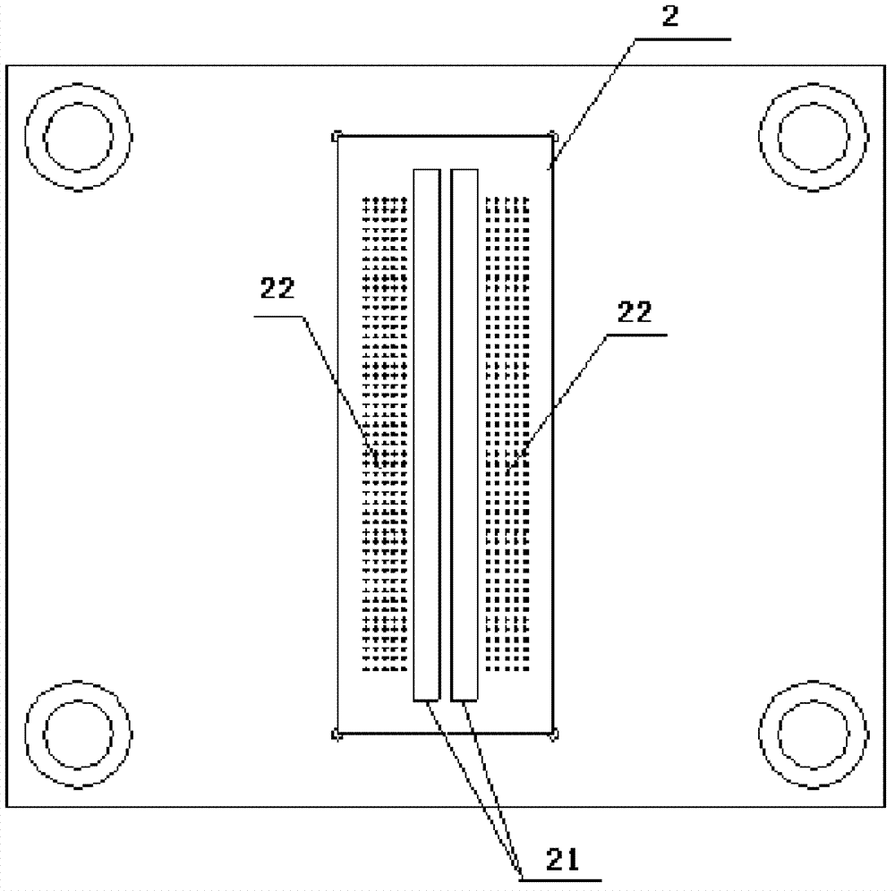
[0021] figure 1 It is a cross-sectional view showing the specific structure of the suction cup clamping device according to the present invention, figure 2 It is a plan view showing the specific structure of the suction panel in the suction cup clamping device according to the present invention. li...


PUM


Abstract

A sucker-type clamping device comprises a clamping body, an adsorption panel and a gas suction device. An elongated laser light outlet is arranged on the clamping body in a through manner, an elongated grooved cavity is arranged near the laser light outlet along the length direction, and the clamping body is further provided with a gas guide channel communicated with the cavity. The adsorption panel is arranged on the upper surface of the clamping body and covers the laser light outlet and the cavity of the clamping body, a suction hole array consisting of a plurality of small through holes is arranged on a portion of the adsorption panel corresponding to the cavity, and an elongated opening is formed on a portion of the adsorption panel corresponding to the laser light outlet. The gas suction device is connected with the gas guide channel through a gas pipe, and gas in the cavity and the gas guide channel can be sucked out. According to the structure, a film material can be neatly placed on the adsorption panel in a clinging manner, deformation of the film material is avoided, and machining precision and machining efficiency are improved.

Description

technical field [0001] The invention relates to the technical field of laser processing, in particular to a sucker type clamping device used in laser processing of thin film materials. Background technique [0002] With the continuous development of society, film materials have been gradually applied in various production and life. Due to the small thickness of the film material itself, poor stiffness and rigidity, and prone to curling and wrinkles, the film material cannot be processed by the usual mechanical processing methods, and laser processing methods are usually used. However, various types of clamping devices are required in the process of processing thin film materials with lasers. [0003] At present, when lasers are used to process thin film materials, the thin film materials are usually clamped and fixed by a pressure plate. When using a pressing plate to fix the film, there will be the following problems: the film material is easily deformed, and the processi...

Claims


Application Information

Patent Timeline
Patent Type & Authority Patents(China)
IPC IPC(8): B23K26/70
Inventor 陈涛申雪飞
Owner BEIJING UNIV OF TECH
Learn More