Pneumatic type pipe bender for small pipe fittings

A pneumatic, pipe bending machine technology, applied in the field of pipe bending machines, can solve the problems of large energy consumption, inconvenient operation and complex structure of the workpiece, and achieve the effects of small footprint, reduced energy consumption and simple structure

Active Publication Date: 2012-07-04
黑龙江北鸥卫浴用品有限公司
View PDF6 Cites 0 Cited by
  • Summary
  • Abstract
  • Description
  • Claims
  • Application Information

AI Technical Summary

Problems solved by technology

However, since most of the commonly used pipe bending machines are used to produce large pipe fittings, the pipe bending machines are large in size and complex in structure, which not only takes up a lot of production space in the factory, but also is inconvenient to operate.
Moreover, this relatively large pipe bending machine mainly uses a three-phase power supply to drive a hydraulic pump to drive the workpiece, which consumes a lot of energy.

Method used


Image

  • Pneumatic type pipe bender for small pipe fittings
  • Pneumatic type pipe bender for small pipe fittings
  • Pneumatic type pipe bender for small pipe fittings

Examples


Embodiment Construction

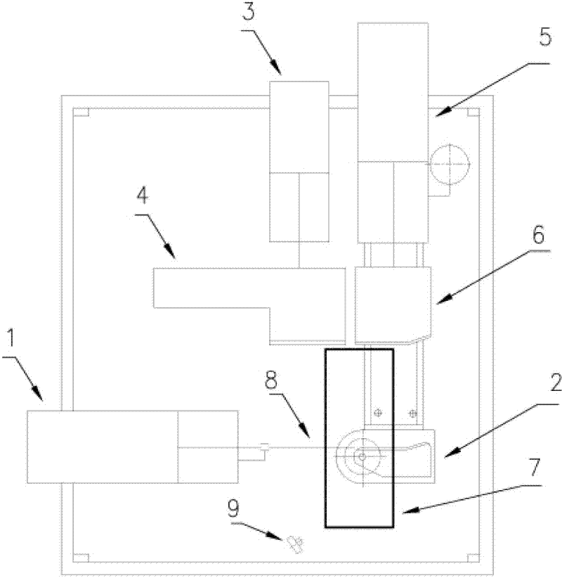
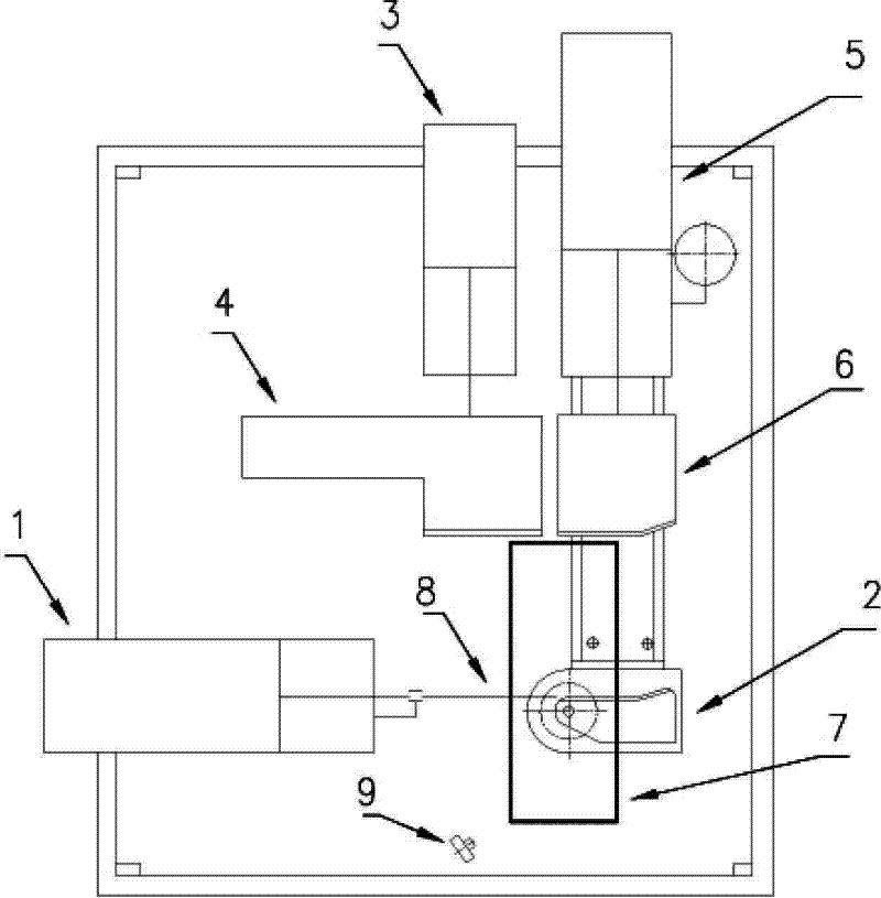
[0015] refer to figure 1 , On the working platform, a small pneumatic pipe bending machine of the present invention includes a pipe bending die 2 and a core-pulling cylinder 1 arranged oppositely. During work, small-sized pipe fitting is enclosed within on the core-pulling rod 8, puts in the pipe groove of bending pipe mold 2 then. On the opposite side of the bending action of the pipe bending die 2, a clamping pipe bending die 6 is vertically opposite to it. Driven by the clamping cylinder 5, the clamping pipe bending die 6 moves forward to cooperate with clamping pipe fittings. A guide clamping die 4 is arranged on the same side as the clamping elbow die 6 . After the action of the clamping elbow mold 6 and the clamping cylinder 5 is delayed for a period of time, the guide clamping mold 4 is driven by the guide cylinder 3 to press the pipe fitting forward to guide the bending and stretching of the pipe fitting. After the guide cylinder 3 is in place, after a delay, the rot...


PUM


Abstract

The invention discloses a pneumatic type pipe bender for small pipe fittings, which comprises a bend mould and a core-pulling air cylinder arranged opposite to each other, a core-pulling rod placed in the bend mould after being sleeved with a tube, a guide clamp mould that is driven by a guide air cylinder to guide the tube during bending and drawing, a clamp bend mould that is driven by a clamp air cylinder to clamp the tube, a rotary air cylinder that drives the bend mould to bend and draw the tube and a positioning block. The clamp air cylinder adopts a structure of a gas-push-oil device. In the invention, the bend mould, the clamp bend mould, the guide clamp mould and the air cylinder that drives the workpiece are designed compactly and the invention is simple in structure and small in occupied area. By designing the clamp air cylinder of key power section in the structure of the gas-push-oil device, the pneumatic type pipe bender of the invention greatly reduces the energy consumption of the bender. The pneumatic type pipe bender of the invention is suitable for meeting the demand of bending small pipe fittings in various plane radians in the field of bathroom industry.

Description

technical field [0001] The invention relates to a pipe bending machine, in particular to a small pneumatic pipe bending machine. Background technique [0002] In the sanitary industry, it is often necessary to bend some circular or square copper and aluminum pipe fittings with small diameters in various plane arcs. However, since most of the commonly used pipe bending machines are used to produce large-scale pipe fittings, the pipe bending machines are large in size and complex in structure, which not only takes up a large production space in the factory, but also is inconvenient to operate. Moreover, this relatively large-scale pipe bending machine mainly uses a three-phase power supply to drive a hydraulic pump to drive the workpiece, which consumes a lot of energy. Therefore, considering the low-cost investment in the production of small pipe fittings in the sanitary industry, it is necessary to design a device that is not only easy to operate, has a small footprint, but...

Claims


Application Information

Patent Timeline
Patent Type & Authority Applications(China)
IPC IPC(8): B21D9/12
Inventor 不公告发明人
Owner 黑龙江北鸥卫浴用品有限公司
Why Eureka
Try Eureka