Eureka AIR delivers breakthrough ideas for toughest innovation challenges, trusted by R&D personnel around the world.

Locking steel plate and collimation assembly component thereof

A technology for assembling components and steel plates, which is applied in the field of medical devices, can solve problems affecting early functional exercise, complete contact with bone surfaces, and central placement of steel plates, etc., to achieve the effect of facilitating functional recovery, reducing oppression and stimulation, and uniform force

Inactive Publication Date: 2012-07-04
马丽昕 +2
View PDF0 Cites 2 Cited by
  • Summary
  • Abstract
  • Description
  • Claims
  • Application Information

AI Technical Summary

Problems solved by technology

At present, the steel plates used clinically for femoral shaft fractures are all the above-mentioned types. Due to the restriction of the sagittal and coronal physiological arcs of the femur, the steel plates cannot be placed in the center of the femoral arc, and cannot be in full contact with the bone surface, resulting in unstable fixation. , there may be bending, breaking, and screw pulling out, resulting in fracture displacement and angulation, and often requires additional external fixation, which affects the shortcomings of early functional exercise

Method used


Image

  • Locking steel plate and collimation assembly component thereof
  • Locking steel plate and collimation assembly component thereof
  • Locking steel plate and collimation assembly component thereof

Examples


Embodiment Construction

[0061] The present invention is described in detail below in conjunction with accompanying drawing:

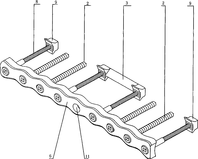
[0062] figure 1 It is a miniature model diagram of the 9-hole locking plate applied to the internal fixation of femoral shaft fractures, in which the plate (6), locking nail (8), single locking (9), interlocking (3), and bone nail (2) are locking plates , assembled together to complete the internal fixation of the fracture. The chain aiming fixer (5) cooperates with the combined screwdriver (4) to assemble the chain (3), so that the locking nail (8) passing through the plate hole (12) and the femur is tightened with the chain (3). The single-lock aiming fixer (1) and the combination screwdriver (4) are used to assemble the single-lock (9), so that the locking nail (8) passing through the plate hole (12) and the femur is screwed with the single-lock (9). The combination screwdriver (4) is mainly used for screwing in and out the locking nail (8) and the bone nail (2). The bon...


PUM


Abstract

The invention belongs to the field of medical instruments, and relates to a femoral shaft fracture internal fixing instrument, which comprises a locking steel plate and a collimation assembly component of the locking steel plate. The locking steel plate comprises a steel plate, a single lock, a combination lock and lock pins, and the collimation assembly component comprises a single lock collimation fixing apparatus, a combination lock collimation fixing apparatus and auxiliary components including bone nails, a bone nail positioning drawing hook, a combined screwdriver and the like. An arc which corresponds to a forward physiological curve of the femur of a patient is longitudinally designed on the steel plate, an arc which corresponds to the transverse diameter of the femur is transversely designed at a position, which is close to a femur surface, of the steel plate, arc-shaped curved surfaces are symmetrically and uniformly distributed on side surfaces of the steel plate, and the steel plate conforms to an arc line of the femur, is placed in the middle of a fracture portion, and contacts with the femur in a limited manner. The combination lock is designed on the inner side of the femur and across a fracture line, the single lock is designed far away from the fracture line, collimation, fixation, drilling and assembling are carried out by the collimation assembly component, and operation is simple and fast. The femoral shaft fracture internal fixing instrument has the advantages that fixation is stable, additional fixation is not required after surgery, and the femoral shaft fracture internal fixing instrument can be used for early-stage functional exercises and is favorable for fracture healing. After fracture healing, a fixing object in the femur can be detached conveniently.

Description

technical field [0001] The invention belongs to the field of medical devices and is an internal fixation device for femoral shaft fractures. Background technique [0002] The femur is the longest tubular bone in the human body. It is one of the main load-bearing bones of the lower limbs. When directly or indirectly subjected to violence that exceeds its own strength and elastic strength, it is prone to deformation and fractures. If the treatment method is not selected properly, it can cause long-term loss of use or disability. At present, clinically, children are often treated with conservative treatment such as bone traction, splint external fixation, and plaster external fixation, while adolescents and adults are often treated with surgical treatment such as metal plates, intramedullary nails, interlocking intramedullary nails, and external fixation brackets (A.H. Crenshaw. Campbell's Encyclopedia of Orthopedic Surgery [M]. Shanghai: Shanghai Translation and Publishing Com...

Claims


Application Information

Patent Timeline
Patent Type & Authority Applications(China)
IPC IPC(8): A61B17/80A61B17/90A61B17/92
Inventor 马丽昕庞贵春庞博
Owner 马丽昕
Why Eureka
Eureka Blog
Learn More