
Centralized monitoring and managing system for optical cable resources

A centralized monitoring and management system technology, applied in transmission monitoring/testing/fault measurement systems, transmission systems, electromagnetic wave transmission systems, etc., can solve problems such as delayed fault processing, hidden internal structure, and inability to store, and reduce faults. Diagnosis and processing time, ensuring safe and stable operation, and reducing human and financial expenditures

Active Publication Date: 2012-06-27
SHANGHAI MUNICIPAL ELECTRIC POWER CO +1
View PDF3 Cites 45 Cited by
  • Summary
  • Abstract
  • Description
  • Claims
  • Application Information

AI Technical Summary

Problems solved by technology

[0004] However, in the traditional detection method, technicians first find the optical cable to be tested on the optical distribution frame (ODF), and then use an optical time domain reflectometer (hereinafter referred to as OTDR equipment) to test it, and then manually To summarize and analyze, the workload is heavy and the expense is high, but the maintenance effect is limited
Moreover, once a communication failure occurs, it is necessary to judge from the transmission inspection first, and then find the faulty section to a certain optical cable, and then arrange technicians to use instruments to test and locate, which will delay the fault test and repair time
In addition, due to the bending of the optical cable during actual laying and the length of the fiber coil reserved in the shaft, etc., the fault location is not accurate enough, which affects the repair speed
In addition, for example, the deterioration of optical fiber quality is a gradual process, and the problem may not be seen from the surface or a single test result, but there are already great hidden dangers in the internal structure, so it is difficult to find out by conventional measurement
[0005] On the other hand, as a passive transmission medium, the optical cable has not yet developed its own detection and alarm function, and can only rely on an external system to monitor and manage its status
However, the existing system for maintaining and managing optical cable network resources is just a simple resource recording system, which lacks the linkage with automatic test equipment, and does not have the maintenance scheduling function
With the help of existing optical fiber transmission equipment, it is possible to find a fault in a certain route, but it is impossible to quantify and locate the location of the fault, which will inevitably delay the time to deal with the fault and cause large economic losses; Provide strong support for optical cable planning
[0006] Moreover, the traditional maintenance management is mainly written, which cannot be directly stored in the computer system, resulting in the accumulation of various reports and data, which is very inconvenient for inspection and comparison.
In addition, since the construction and use are different units or departments, there may be some differences in the data collected in the organization of testing and acceptance, which will leave flaws for the later analysis of optical cable status changes and the formulation of update plans.

Method used


Image

  • Centralized monitoring and managing system for optical cable resources
  • Centralized monitoring and managing system for optical cable resources
  • Centralized monitoring and managing system for optical cable resources

Examples


Embodiment Construction

[0047] The specific embodiments of the present invention will be described below in conjunction with the accompanying drawings.

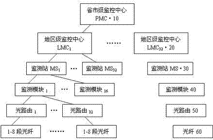
[0048] The centralized monitoring and management system for optical cable resources in the present invention is a multi-level and layered management platform. exist figure 1 In the illustrated embodiment, it includes a secondary monitoring and management platform. The first level is a provincial and municipal monitoring center 10 (hereinafter referred to as PMC), and the second level is several regional monitoring centers 20 (hereinafter referred to as LMC) connected to it. ); Below the monitoring management platform is a layer of monitoring operation platform framework, including several monitoring stations MS·30 connected behind each LMC·20.

[0049] Between the two-level monitoring center PMC and LMC, between the regional monitoring center LMC and the monitoring station MS 30, can be connected through wired networks such as DDN, DCN, TCP / IP, or ...


PUM


Abstract

The invention relates to a centralized monitoring and managing system for optical cable resources. A system structure based on two stages of monitoring and managing platforms and a layer of monitoring and operating platform is at least regulated and controlled by the two stages of monitoring centers of a province and city stage and a region stage, and the monitoring of various modes of optical time domain reflectometer (OTDR) test, light power test, linking test thereof and the like is also provided to an optical fiber in use or a standby fiber in an optical fiber network at an executing lay by a plurality of monitoring stations correspondingly. The system also provides an abundant system managing function; especially, a resource topology drawing of an entire network can be drawn according to the configuration parameter of the system; and the operation of quick and accurate positioning during maintenance and fault examination is assisted by utilizing a geographic information system (GIS) technology. Therefore, according to the system disclosed by the invention, the expense of manpower and financial resources for maintenance and management can be effectively reduced, and the time of fault diagnosis and treatment is effectively shortened, so that the safe and stable running of the entire network is ensured.

Description

technical field [0001] The invention particularly relates to a centralized monitoring and management system for optical cable resources. Background technique [0002] Because optical fiber communication has a series of advantages in terms of transmission distance, transmission rate and stability, its application has increasingly penetrated into various fields of national economy and daily life, and has become an indispensable link. For example, power optical cables have three main purposes: one is relay protection data exchange and command transmission in power grid operation; the other is daily communication work of power grid system and providing transmission channel convenience for telecom operators; Indicates signal delivery. [0003] Since the optical fiber is a physical object, it has a lifespan problem of performance degradation. In addition to the impact of various accidents such as bad weather and external shocks, it is easy to cause damage to the optical cable, in...

Claims


Application Information

Patent Timeline
IPC IPC(8): H04B10/08H04B10/07
Inventor 林亦雷杨铭卢士达
Owner SHANGHAI MUNICIPAL ELECTRIC POWER CO
Learn More