
Follower rest for hydraulic automatically centering, automatically compensating and surface rolling

An automatic centering and automatic compensation technology, which is applied in the direction of large fixed members, metal processing machinery parts, metal processing equipment, etc., can solve the problem of unpublished exact surface roughness index and the inability to guarantee the accurate clamping force and clamping force of the workpiece. Inaccurate control and other problems, to achieve the effect of eliminating the phenomenon of over-loose or over-tight, simple structure, and loose tool requirements

Inactive Publication Date: 2012-06-27
CHANGCHUN UNIV OF SCI & TECH
View PDF11 Cites 23 Cited by
  • Summary
  • Abstract
  • Description
  • Claims
  • Application Information

AI Technical Summary

Problems solved by technology

The existing technical problem is that the solution does not disclose that it can be applied to the processing of different spindle speeds, does not disclose the exact surface roughness index, and cannot guarantee the accurate clamping force on the workpiece. If a manual clamping mechanism is used, it will There is the problem of inaccurate clamping force control. Under the condition of uneven force, the workpiece will obviously bend, which will reduce the machining accuracy.

Method used


Image

  • Follower rest for hydraulic automatically centering, automatically compensating and surface rolling
  • Follower rest for hydraulic automatically centering, automatically compensating and surface rolling
  • Follower rest for hydraulic automatically centering, automatically compensating and surface rolling

Examples


Embodiment 1

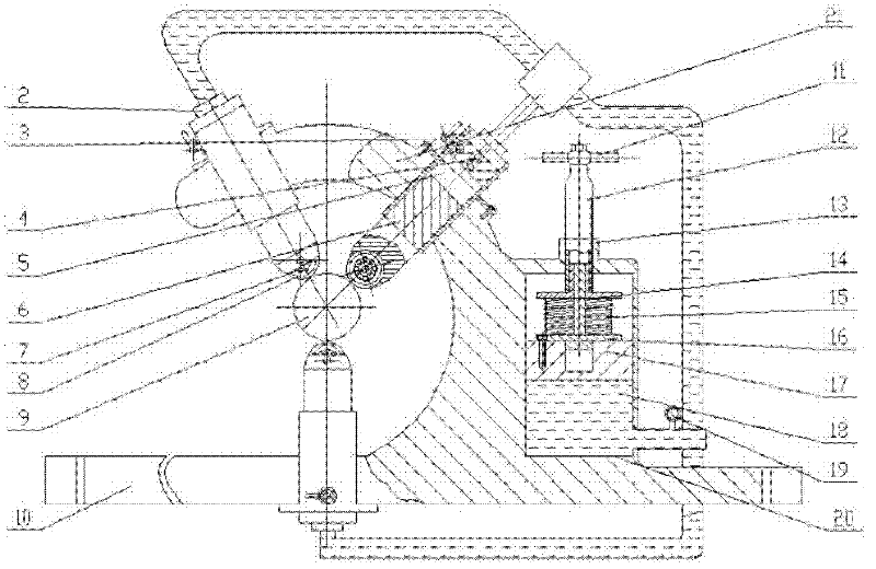
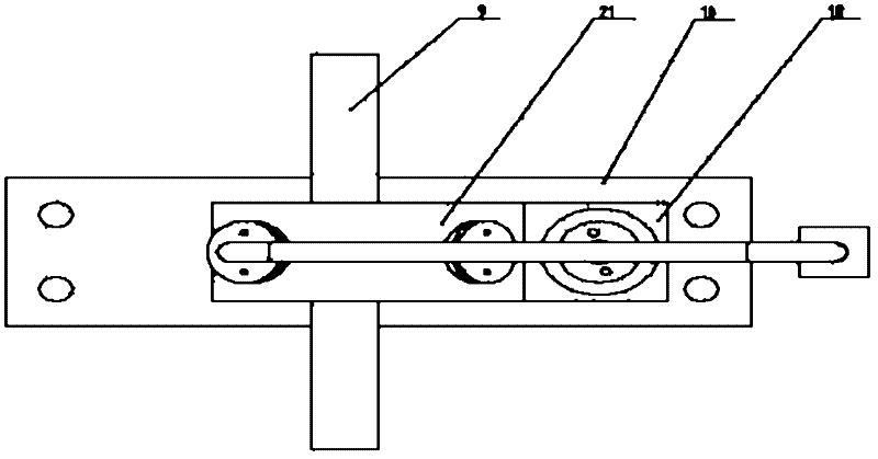
[0017] Example 1 as figure 1 As shown, a hydraulic automatic centering, automatic compensation and surface rolling heel tool holder includes 3 heel claw units, a hydraulic unit and a frame unit with the same structure; the frame unit includes a base plate 10, a large hydraulic cylinder Seat 20 and arc-shaped cantilever 21; large hydraulic cylinder seat 20 and arc-shaped cantilever 21 are cast on the base plate 10 by means of integral casting, and arc-shaped cantilever 21 is above one side of large hydraulic cylinder seat 20; 20 is processed into a large hydraulic cylinder 18; the bottom plate 10 is connected and fixed with the small supporting plate of the machine tool guide rail with bolts;

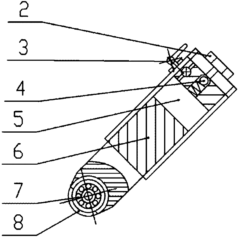
[0018] The axes of the three heel claw units are located in the same plane, and their extension lines intersect at one point. The heel claw unit installed on the bottom plate 10 is placed vertically, and the other two heel claw units are placed on the arc cantilever 21 In the hole, thre...


PUM


Abstract

The invention provides a follower rest for hydraulic automatically centering, automatically compensating and surface rolling. Because three follower claw units enable workpiece to stress from three points, the three force forms a plane concurrent force system to achieve balance, thereby eliminating the shortcoming that the workpiece is easy to deform and bend caused by rolling by a single wheel. When the follower rest is used, the pressure is manually adjusted; and the too loose or too tight phenomenon of the common follower rest can be eliminated. When the diameter of the workpiece becomes little after turning, a hydraulic unit adjusts the pressure of the follower claw units to the workpiece so as to automatically compensate. When the surface size precision and the surface quality requirements of the workpiece are high, the hydraulic oil pressure is appropriately adjusted, so that three rolling wheels of the follower claw units simultaneously and evenly press the workpiece; the rotation of the workpiece drives the rolling wheels to rotate; and the follower rest rolls the surface of the workpiece during longitudinal moving. The follower rest provided by the invention has the functions of automatically centering, automatically compensating and pressing surface when the follower rest is used for turning an elongate shaft. The follower rest is convenient to use, high in stability and has relaxed requirements to tools.

Description

technical field [0001] The invention relates to a hydraulic automatic centering, automatic compensation and surface rolling tool rest, which is used for turning and processing slender shafts and belongs to the technical field of mechanical processing equipment. Background technique [0002] The tool rest is an auxiliary device for radially supporting the rotating workpiece. During processing, it moves along the axial direction of the workpiece together with the tool. With the development of precision manufacturing, more and more slender parts are processed with high precision requirements. However, when the slender parts with high surface roughness requirements have high friction and are easy to wear during processing, it becomes a technical problem to add lubricating oil. A Chinese patent with the application number CN200920276063.4 discloses a technical solution titled "Rolling Three-jaw Adjustable Heel Tool Rest". The scheme consists of a bracket, a C-shaped frame fixe...

Claims


Application Information

Patent Timeline
Patent Type & Authority Applications(China)
IPC IPC(8): B23Q1/76B23P9/02
Inventor 李晓舟张臣顾佳超孙岳龙志伟
Owner CHANGCHUN UNIV OF SCI & TECH
Learn More