
Threshing device of harvester

A technology of threshing device and harvester, which is applied in threshing equipment, agricultural machinery and implements, application, etc. It can solve the problems of large conveying trough and main threshing drum, increase the length of threshing drum, prolong threshing time, etc., so as to prolong the cleaning time , prolong the threshing time, increase the effect of residence time

Inactive Publication Date: 2012-06-27
ZHONGJI SOUTHERN MACHINERY
View PDF5 Cites 11 Cited by
  • Summary
  • Abstract
  • Description
  • Claims
  • Application Information

AI Technical Summary

Problems solved by technology

[0002] At present, there are two kinds of threshing mechanisms of common harvesters, one is the threshing mechanism placed perpendicular to the walking direction of the harvester, and the other is the threshing mechanism placed parallel to the walking direction of the harvester; the threshing mechanisms of these two harvesters are both Horizontally placed, although the latter adopts a vertically arranged threshing mechanism, which greatly increases the length of the threshing drum and prolongs the threshing time compared with the horizontally arranged threshing mechanism, but the corner between the conveying trough and the main threshing drum is relatively large, and it is difficult to handle during harvesting operations. The transfer of crops from the conveying trough to the threshing mechanism is not smooth, the resistance is large, and blockage is prone to occur

Method used


Image

  • Threshing device of harvester
  • Threshing device of harvester
  • Threshing device of harvester

Examples


Embodiment Construction

[0036] The present invention will be described in further detail below in conjunction with the accompanying drawings.

[0037] This specific embodiment is only an explanation of the present invention, and it is not a limitation of the present invention. Those skilled in the art can make modifications to this embodiment without creative contribution as required after reading this specification, but as long as they are within the rights of the present invention All claims are protected by patent law.

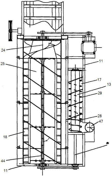
[0038] Such as Figure 1-9 As shown, a harvester is provided with a harvesting mechanism 8, a conveying trough 2 and a threshing device sequentially along the front end of the harvester to the rear end.

[0039] The threshing device comprises an underframe 5, a threshing frame 11 fixed on the underframe 5, a main threshing mechanism and a multiple threshing mechanism which are all connected to the threshing frame 11 and arranged along the walking direction of the harvester, and f...


PUM


Abstract

The invention relates to a harvester, in particular to a threshing device of a harvester. According to the technical scheme, the threshing device of the harvester comprises an underframe, a threshing frame, a main threshing mechanism, a rethreshing mechanism, a separation, cleaning and vibration screen and an impurity lifting screw, wherein the threshing frame is fixed on the underframe, both the main threshing mechanism and the rethreshing mechanism are connected to the threshing frame and disposed along the travelling direction of the harvester, the separation, cleaning and vibration screen is fixedly connected to the threshing frame and positioned between the underframe and the main threshing and rethreshing mechanisms, and the impurity lifting screw is disposed between the position below the rear end of the separation, cleaning and vibration screen and the rethreshing mechanism. The main threshing mechanism comprises a main threshing roller, a large concave screen and a main roller cover, wherein the main threshing roller is hinged to the threshing frame, the large concave screen is fixed to the threshing frame and encloses the main threshing roller, and the main roller cover covers an opening of the large concave screen. The main threshing roller is slantingly disposed along the advancing direction of the harvester. A corner between the main threshing roller and a conveying chute of the threshing device compared with the prior art is reduced, so that conveying of crops is smooth, and the shortages of the prior art are made up.

Description

technical field [0001] The invention relates to a harvester, in particular to a threshing device of the harvester. Background technique [0002] At present, there are two kinds of threshing mechanisms of common harvesters, one is the threshing mechanism placed perpendicular to the walking direction of the harvester, and the other is the threshing mechanism placed parallel to the walking direction of the harvester; the threshing mechanisms of these two harvesters are both Horizontally placed, although the latter adopts a vertically arranged threshing mechanism, which greatly increases the length of the threshing drum and prolongs the threshing time compared with the horizontally arranged threshing mechanism, but the corner between the conveying trough and the main threshing drum is relatively large. The transfer of crops from the conveying trough to the threshing mechanism is not smooth, the resistance is large, and blockage is prone to occur. Contents of the invention [...

Claims


Application Information

Patent Timeline
Patent Type & Authority Applications(China)
IPC IPC(8): A01F12/18
Inventor 曾联黄江军李颖聪
Owner ZHONGJI SOUTHERN MACHINERY
Learn More