
Multifunctional current impulse transmitter and control method

A technology of current pulse and transmitter, which is applied in the control/regulation system, protection against overcurrent, DC power input conversion to DC power output, etc. It can solve the problems of increased complexity of the transmission system, and improve efficiency, The effect of narrowing the range of variation

Inactive Publication Date: 2012-06-20
JILIN UNIV
View PDF2 Cites 17 Cited by
  • Summary
  • Abstract
  • Description
  • Claims
  • Application Information

AI Technical Summary

Problems solved by technology

Increased complexity of the launch system due to the need for an auxiliary power supply

Method used


Image

  • Multifunctional current impulse transmitter and control method
  • Multifunctional current impulse transmitter and control method
  • Multifunctional current impulse transmitter and control method

Examples


Embodiment Construction

[0028] Below in conjunction with accompanying drawing and embodiment the present invention is described in further detail:

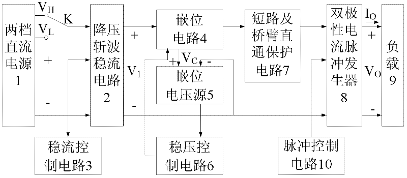
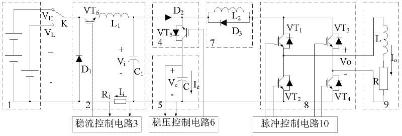
[0029] The multi-functional current pulse transmitter is composed of two gears of DC power supply 1, the positive pole is connected through the switch K to the step-down chopper current stabilization circuit 2, the clamping circuit 4, the short circuit and bridge arm direct protection circuit 7, and the bipolar current pulse generator 8 It is connected with the load 9, the steady-current control circuit 3 is connected with the step-down chopper steady-state circuit 2, the clamping circuit 4 is connected with the constant-voltage control circuit 6 through the clamping voltage source 5, and the negative pole of the two-speed DC power supply 1 is subjected to step-down chopping The current stabilization circuit 2, the bipolar current pulse generator 8 are connected to the load 9, the input negative pole of the clamp voltage source 5 is connected to the outpu...


PUM


Abstract

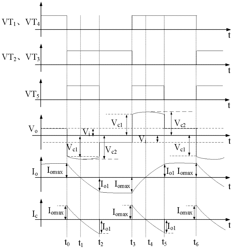
The invention relates to a multifunctional current impulse transmitter and a control method. The transmitter is formed according to the following method: the positive electrode of a two-gear direct current power supply is connected with a depressurization chopping constant-current circuit, a clamping circuit, a short-circuit and bridge arm direct connection protective circuit, a bipolar current impulse generator and a load through a switch K; and the negative electrode of the two-gear direct current power supply is connected with the load through the depressurization chopping constant-current circuit and the bipolar current impulse generator. According to the invention, the two-gear direct current power supply is adopted to coarsely regulate an output voltage; the depressurization chopping constant-current circuit is used so as to precisely regulate the output voltage, thereby reducing the variation range of the duty ratio of the depressurization chopping constant-current circuit and improving efficiency; the clamping circuit can perform bootstrap on a capacitor of a clamping voltage source to generate a high voltage in no need of improving the voltage of a direct current power supply or providing an auxiliary power supply; the linearity and the steepness of the failing edge of the current impulse are changed through regulating the voltage of the linear clamping voltage source; and the short-circuit and bridge arm direct connection protective circuit is matched with an impulse controller, so that the circuit has a self-repairing function after a failure is removed.

Description

Technical field: [0001] The invention relates to an electrical prospecting instrument in geophysical prospecting, in particular, it is suitable for a coil whose load is an equivalent inductance of hundreds of μH-2mH and an equivalent resistance of 0.3-2Ω, and an equivalent inductance of 1mH-7mH and an equivalent resistance of 10 ~80Ω current pulse transmitter and control method. Background technique: [0002] In geophysical exploration, the electrical instrument corresponding to the electrical exploration method has the following two main loads: one is the coil surrounded by the transmitting wire, and the other is the ground between the two pits. The former is called a magnetic source, the load equivalent inductance is several hundred μH ~ 2mH, and the equivalent resistance is 0.3 ~ 2Ω; the latter is called an electrical source, the load equivalent inductance is 1mH ~ 7mH, and the equivalent resistance is 10 ~ 80Ω , the equivalent inductance is mainly determined by the indu...

Claims


Application Information

Patent Timeline
Patent Type & Authority Applications(China)
IPC IPC(8): H02M7/537H02M3/156H02H3/08
Inventor 林君薛开昶周逢道于生宝吴勇刘长胜
Owner JILIN UNIV
Learn More