Target location method in specific environment and based on active radio frequency identification device (RFID) and system thereof

An RFID tag, target positioning technology, applied in instruments, induction record carriers, computer parts, etc., can solve the problems of inconvenience, reduced positioning accuracy, indoor environment damage, etc., to reduce complexity and cost, and achieve high-precision positioning. , the effect of reducing the number of settings

Active Publication Date: 2012-06-20
KUNCHEN TECH CO LTD
View PDF5 Cites 12 Cited by
  • Summary
  • Abstract
  • Description
  • Claims
  • Application Information

AI Technical Summary

Problems solved by technology

Chinese invention patent (application number 200910051180.5) discloses an RFID indoor positioning system and technology. The invention adopts a short-range RFID reader and antenna placed on the robot chassis, and a passive RFID tag is placed on the ground of the robot's movement area as positioning. For reference, the positioning of the mobile robot is realized by reading the information in the RFID tag through the RFID reader, but this method needs to arrange tags in the movement area in advance, which will cause a certain degree of damage to the indoor environment and is inconvenient to implement
[0003] Chinese Invention Patent (Application No. 201110005728.X) discloses a real-time positioning system, which draws the tag movement trajectory and calculates the moving speed according to the order, information intensity value and time difference of the tags read by several adjacent RFID base stations , for indoor positioning, the signal will experience reflection and refraction of obstacles during the propagation process, resulting in multiple propagation paths of the signal. In the case of serious multipath, the positioning accuracy of this positioning method is greatly reduced

Method used


Image

  • Target location method in specific environment and based on active radio frequency identification device (RFID) and system thereof
  • Target location method in specific environment and based on active radio frequency identification device (RFID) and system thereof

Examples


Embodiment

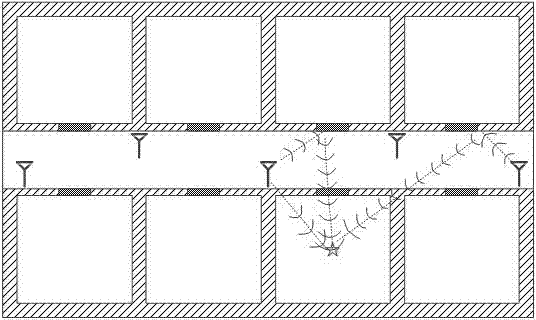
[0032] Such as figure 1 As shown, suppose there are 8 rooms in a building, and the target is located in one of the houses. The overall size of the building is 12 meters long x 8 meters wide x 2.8 meters high, the outer wall thickness is 36 cm, and the internal partition wall The thickness is 12 cm, the wall dielectric constant is 4.2, the conductivity is 0.01, and the permeability is 1. The 8 receiving antennas are placed in the corridor, evenly distributed, and the target is placed in a certain room. The fixed antenna adopts a bow tie electric dipole Sub-wideband antenna, -3dB bandwidth is 200-400MHz. RFID card readers and tags can adopt general solutions such as Nordic's nRF2401 solution or Texas Instruments' CC1100 solution.

[0033] First, the RFID card reader transmits positioning instructions through a fixed antenna. After receiving the positioning instructions, the measured target emits positioning pulse signals. , Its center frequency is 300MHz, and the bandwidth is abo...


PUM

PropertyMeasurementUnit
Center frequencyaaaaaaaaaa
Bandwidthaaaaaaaaaa

Abstract

The invention discloses a target location method in specific environment and based on an active radio frequency identification device (RFID) and a system thereof, which adopt the mode of time inversion, are capable of conducting real-time high-accuracy location on an active RFID label on the premise that indoor environment is not modified, conduct simulation of the communication process of electromagnetic wave after the time inversion in a simulation environment, determine the position of a target to be located by reading peak value of energy of an electromagnetic field, and overcome the shortcoming that the traditional location accuracy relies on complexity of environment. The time inversion process is not finished on the target to be located, so that complexity and cost of the target to be located are reduced. A real transmitter is not required, so that complexity and cost of a signal processing mechanism are reduced. The simulation environment built in the signal processing mechanism corresponds to the real specific environment, and the multi-diameter and multi-scattering conditions can all be fully utilized in the time inversion process. Compared with the prior location mode, the method and the system reduce arrangement number of fixed antenna and reduce system cost.

Description

Technical field [0001] The invention relates to a positioning method and system, in particular to a target positioning method and system based on active RFID in a specific environment. Background technique [0002] The demand for various location-based services in the indoor environment is increasingly urgent. Real-time positioning of items in the logistics field is conducive to improving the management level of logistics; real-time positioning in the public security field is conducive to maintaining social safety; in daily life , Can help people understand the status of children, pets, objects, etc. However, with existing satellite positioning systems, in indoor environments or densely built areas, satellite signals are blocked by obstacles, making it difficult to locate effectively. In addition, indoor positioning technologies include infrared technology and ultrasonic technology, but the signal needs line-of-sight propagation. The positioning range is relatively limited. Rad...

Claims


Application Information

Patent Timeline
IPC IPC(8): G06K7/00
Inventor 赵志钦朱晓章杨伟张胤欧阳骏聂在平
Owner KUNCHEN TECH CO LTD
Why Eureka
Try Eureka