
Test system and method for mode and vibration of self-supporting tower and large-span power transmission tower

A technology for vibration testing and transmission towers, which is applied in the field of power systems and can solve problems such as blank test modal analysis work

Active Publication Date: 2012-06-20
JIANGSU FRONTIER ELECTRIC TECH +2
View PDF7 Cites 28 Cited by
  • Summary
  • Abstract
  • Description
  • Claims
  • Application Information

AI Technical Summary

Problems solved by technology

At present, there is very little field measurement data on the vibration mode of the prototype of the transmission tower, and the experimental modal analysis work of the whole tower is almost blank.

Method used


Image

  • Test system and method for mode and vibration of self-supporting tower and large-span power transmission tower
  • Test system and method for mode and vibration of self-supporting tower and large-span power transmission tower
  • Test system and method for mode and vibration of self-supporting tower and large-span power transmission tower

Examples


Embodiment Construction

[0021] The present invention will be further described below in conjunction with the accompanying drawings.

[0022] Measurement items include:

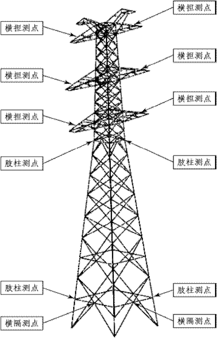
[0023] a) Vibration measurement of transmission tower limbs, diaphragms and crossarms;

[0024] b) The first 6 modal frequencies and mode shapes in the longitudinal X and transverse Y directions of the transmission tower.

[0025] Measuring point layout:

[0026] a) The measuring point of the limb column is two directions (longitudinal X axis and horizontal Y axis) of two points on two opposite corners of the limb column, and the height of the measuring point is the lower transverse partition and the lower part of the lower cross arm. The measuring points of the diaphragm are the X-axis and Y-axis directions in the middle of two adjacent main rods. The cross-arm measuring points are the X-axis and Y-axis directions of the two extended ends of each cross-arm.

[0027] b) The number of measuring points for the overall modal test of...


PUM


Abstract

The invention discloses a test system and method for mode and vibration of a self-supporting tower and a large-span power transmission tower. The test system is characterized by comprising a sensor, wherein the sensor is connected with a signal conditioner; the signal conditioner is connected with a digital signal collecting box; a digital signal collector is connected with a computer; the digital signal collector is provided with eight channels; and an auto-power spectrum analysis module, a cross-power spectrum analysis module and an environmental motivation mode analysis module are arranged in the computer. On the basis of an environmental motivation method, a method for fixing a reference point and moving a measured point is utilized to test mode parameters and vibration of a soaring power transmission tower. Besides, corresponding hardware equipment and software programs are utilized to ensure that the environmental motivation method can be used for performing off-line mode test and analysis for a power transmission tower model.

Description

technical field [0001] The invention relates to a transmission tower modal and vibration testing system and a method thereof, belonging to the technical field of power systems. Background technique [0002] The frequency domain relationship between the vibration response signal of a structure under a certain vibration excitation and the excitation signal is the frequency response function of the structure. According to the transfer function on all the characteristic degrees of freedom of the structure, the modal parameters of the structure can be identified through modal parameter fitting and identification software: natural frequency, natural mode shape and modal damping. Modal parameters, also known as the dynamic fingerprint of a structure or machine, are the main state parameters that characterize the dynamic reliability of a structure. [0003] For large structures such as bridges, high-rise buildings, and transmission towers, it is difficult to use artificial excitati...

Claims


Application Information

Patent Timeline
IPC IPC(8): G01H1/12G01H1/14
Inventor 卢修连刘晓锋黄磊孙和泰
Owner JIANGSU FRONTIER ELECTRIC TECH
Learn More