
Flow control device

A technology of flow control device and diversion groove, which is used in manufacturing tools, glass manufacturing equipment, glass furnace equipment, etc. The effect of improving the yield of good products

Inactive Publication Date: 2012-06-20
CDGM OPTICAL GLASS
View PDF3 Cites 0 Cited by
  • Summary
  • Abstract
  • Description
  • Claims
  • Application Information

AI Technical Summary

Problems solved by technology

Because the gate has been in contact with the glass liquid for a long time, some components of the glass liquid will volatilize at high temperature, and the volatiles will accumulate on the gate and other peripheral equipment. When the accumulation reaches a certain level, droplets will flow to the glass liquid along the periphery In the process, especially on the gate near the tin bath, due to the poor sealing around the gate, the air entering the channel will react with the tin vapor from the tin bath to form tin compounds, which are commonly known as " Tin ash”, the liquid droplets formed by the glass volatile condensate and tin ash are different from the homogeneous glass liquid below because of the temperature and composition, so they cannot form a uniform composition with the glass again, and often exist in the glass as stones and other defects , which not only affects the yield of glass, but even causes glass plate breakage accidents in severe cases, which is not conducive to safe production and increased glass output.

Method used


Image

  • Flow control device
  • Flow control device
  • Flow control device

Examples


Embodiment Construction

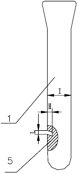
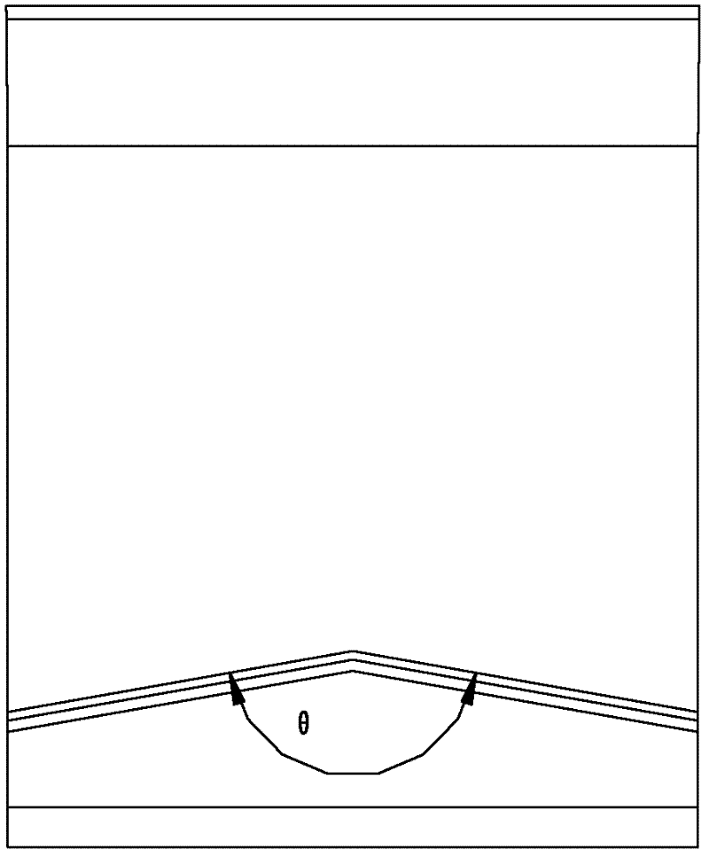
[0017] In the present invention, a diversion structure is arranged on the flashboard 1 . The diversion structure is that a diversion groove 5 is arranged on one side of the flashboard 1, such as figure 1 and figure 2 shown. The diversion groove 5 is preferably a herringbone groove with an upward slant, and the top of the herringbone is located in the middle of the gate 1 . The herringbone angle θ of the diversion groove 5 is 120-170°, preferably 160°; the width L of the diversion groove 5 is 10-100mm, and the preferred width is 57mm; the depth H of the diversion groove 5 does not exceed the gate 1 / 4 of the thickness I of plate 1. Through the guide groove 5, the droplets formed by the volatile condensation of the molten glass 3 and the adhesion of tin ash can be guided to both sides of the channel.

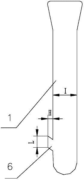
[0018] The above-mentioned diversion structure can also be provided with a diversion protrusion 6 on one side of the shutter 1, such as image 3 and Figure 4 shown. The di...


PUM

PropertyMeasurementUnit
widthaaaaaaaaaa

Abstract

The invention provides a flow control gate which ensures that liquid drops cannot flow to the middle position of glass liquid. A flow control device comprises a gate, wherein a flow guide structure is arranged on the gate. The flow guide structure is arranged on the gate, the flow of volatile can be guided to the lateral part of a channel by the liquid drops formed by glass volatile and condensate and tin ash through the flow guide structure, the quality of glass cannot be influenced by inflow of the residual volatile in the process of forming the glass, and a glass strip on the lateral part of the glass can be cut off through longitudinal cutting in the cold end process, so the yield of a non-defective glass product is improved.

Description

technical field [0001] The invention relates to a device for glass flow control in the float glass industry, in particular to a flow control gate. Background technique [0002] At present, in the float glass industry, in order to control the flow of glass flowing into the tin bath, one or more flow control gates are generally added to the passage between the melting furnace and the tin bath. Uninterrupted flow control to stabilize the output required for tin bath forming. Because the gate has been in contact with the glass liquid for a long time, some components of the glass liquid will volatilize at high temperature, and the volatiles will accumulate on the gate and other peripheral equipment. When the accumulation reaches a certain level, droplets will flow to the glass liquid along the periphery. In the process, especially on the gate near the tin bath, due to the poor seal around the gate, the air entering the channel will chemically react with the tin vapor from the ti...

Claims


Application Information

Patent Timeline
Patent Type & Authority Applications(China)
IPC IPC(8): C03B18/16
CPCC03B5/267
Inventor 陈筱丽冯宏宋纯才杨云郭富强
Owner CDGM OPTICAL GLASS
Learn More