
Welding equipment and use method thereof

A welding equipment and welding torch technology, which is applied in the field of welding equipment for narrow-gap automatic welding in the main circuit of nuclear power plants, can solve the problems of complicated replacement, complicated gas circuit, and unfavorable adjustment by operators, so as to reduce the space requirement for welding and ensure the The effect of welding quality and improving environmental protection benefits

Active Publication Date: 2014-09-10
CHINA NUCLEAR IND 23 CONSTR
View PDF9 Cites 0 Cited by
  • Summary
  • Abstract
  • Description
  • Claims
  • Application Information

AI Technical Summary

Problems solved by technology

The disadvantages of this welding torch are: 1. In order to play a protective effect, the flat welding torch is generally made longer in the circumferential direction, so it is inconvenient to observe the molten pool during the welding process, which is not conducive to the adjustment of the operator; 2. . Due to the need to go deep into the weld seam, the height of the flat welding torch is generally relatively large, about 70-80mm, but when it is welded to the surface of the weld seam, the space required is relatively large, which is not conducive to the implementation of welding at the nuclear power site; 3. The welding torch must be cooled by water cooling, but the water cooling method often divides the protection of the tungsten electrode into two parts, the gas circuit is relatively complicated
During the whole welding process, the gas mask needs to be replaced at least three times, which is very tedious
In addition, in addition to replacing the gas cover, the electrode holder with the electrode must also be replaced every time. The electrode holder is an assembly composed of a housing, a connection knob and an electrode fastener, so the replacement is also quite complicated.
[0008] In addition, the welding equipment developed by the French company FRAMATOME did not give a specific solution to the cooling problem of the lower gun body of the flat welding torch.
[0009] In view of the fact that the main circuit of the nuclear power plant has high requirements on welding quality, and the three welding equipment or welding methods described above will bring many problems to the welding quality, it is necessary to develop a new welding equipment to improve the welding quality

Method used


Image

  • Welding equipment and use method thereof
  • Welding equipment and use method thereof
  • Welding equipment and use method thereof

Examples


Embodiment Construction

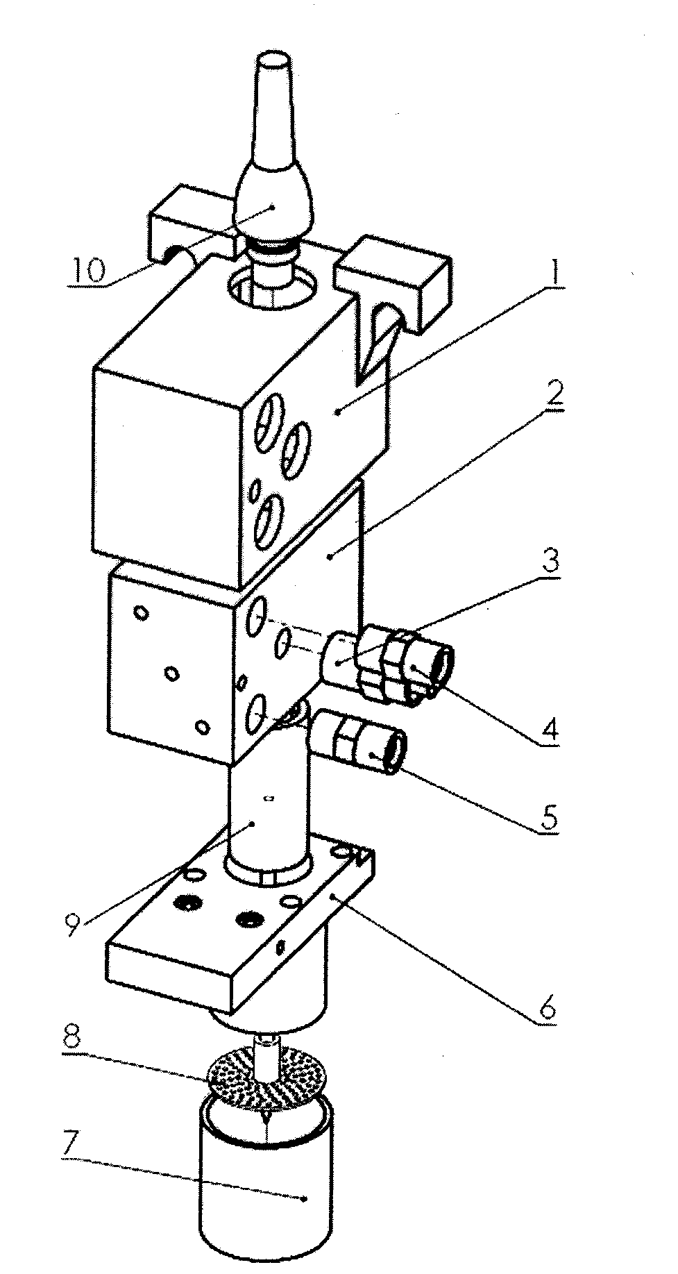
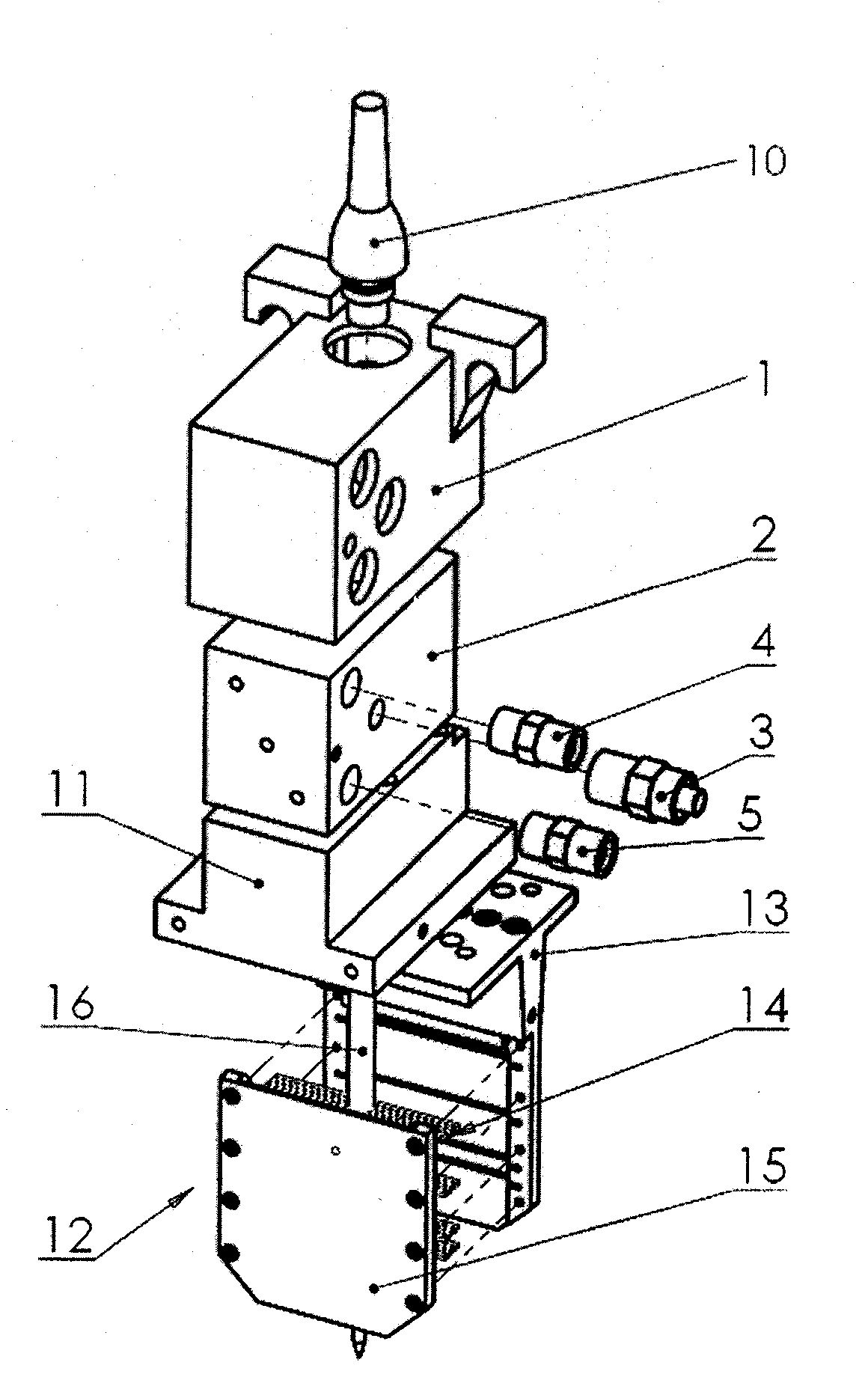
[0033] Welding equipment of the present invention is equipped with two kinds of welding torches, namely as figure 1 Standard torches shown and as figure 2 The flat welding torch shown. When the welding seam is deep, the flat welding torch is used first, that is, the welding equipment is installed as figure 2 The flat welding torch shown is used for welding; when the welding seam reaches a certain height, that is, when the welding seam is shallow, change it figure 1The standard torch shown continues to weld until the weld is complete. For workplaces with narrow welds, especially for the main circuit of nuclear power plants, after a large number of calculations and experimental results, the inventor found that when the weld depth is ≥ 25-30mm, use a flat welding gun to perform close-range protection welding on the molten pool; As the weld seam is continuously filled, when the weld seam depth is <25-30mm, replace it with a standard welding torch for welding. This welding eq...


PUM

PropertyMeasurementUnit
thicknessaaaaaaaaaa
thicknessaaaaaaaaaa
heightaaaaaaaaaa

Abstract

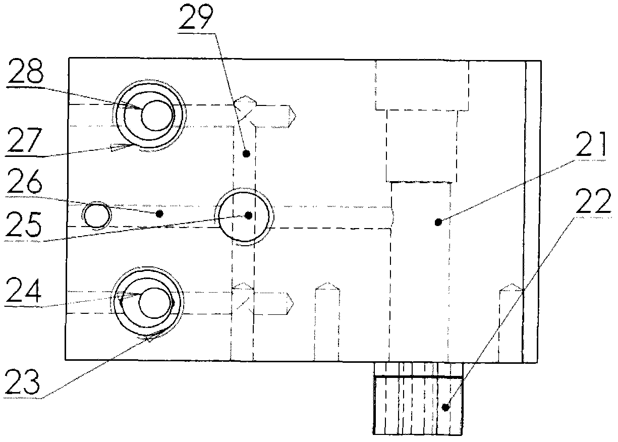
The invention relates to the field of welding, in particular to welding equipment of a nuclear power station main loop, and a use method of the welding equipment. In order to solve the welding quality problem and the problem of high cost, the welding equipment is provided and comprises two welding torches: a flat welding torch and a standard welding torch; when a deep part of a welding seam is welded, the flat welding torch is used for welding, and when a shallow part of the welding seam is welded, the standard welding is used for welding; the flat welding torch comprises an insulating case, a welding torch base body, a middle insulator, a lower gun body and an electrode assembly which sequentially penetrates through the components, and a channel for cooling water circulation and a channel through which a protective gas can pass are arranged inside the welding torch basal body and the middle insulator and the upper part of the lower gun body; and the lower gun body is in a hollow flat shape except a connecting part of the lower gun body, and an insulating pipe through which an electrode can pass, and a gas strainer capable of allowing the protective gas to be advected are arranged inside the flat structure. The welding equipment both improves the welding quality and saves the cost.

Description

technical field [0001] The invention relates to the field of welding, in particular to welding equipment for automatic welding of narrow gaps in the main circuit of a nuclear power plant and a method for using the same. Background technique [0002] Narrow-gap automatic welding of the main circuit of nuclear power plants is a key technology in the installation and construction of nuclear power plants. The wall thickness of this welded pipe is usually between 60 and 100mm, and the weld seam is usually between 6 and 10mm due to the shrinkage during the welding process. In view of moderate heat input during welding, high welding efficiency, and suitable for all-position welding, narrow-gap automatic welding has been vigorously promoted and applied during the installation and construction of nuclear power plants. [0003] However, there are some technical difficulties in the existing narrow-gap automatic welding of the main circuit of nuclear power plants. For example, the adj...

Claims


Application Information

Patent Timeline
Patent Type & Authority Patents(China)
IPC IPC(8): B23K9/28B23K9/24B23K9/00
Inventor 郭彦辉胡广杰王海东张兰国董玉川王峰韩乃山
Owner CHINA NUCLEAR IND 23 CONSTR
Learn More