
Flat-panel display panel and manufacturing method thereof

A flat-panel display and panel technology, applied in optics, instruments, electrical components, etc., can solve the problems of affecting the aperture ratio, increase the cost, reduce the yield of the assembly process, etc., and achieve the effect of increasing the shading area

Inactive Publication Date: 2012-06-13
SHENZHEN CHINA STAR OPTOELECTRONICS TECH CO LTD
View PDF7 Cites 11 Cited by
  • Summary
  • Abstract
  • Description
  • Claims
  • Application Information

AI Technical Summary

Problems solved by technology

However, with this structure, the alignment accuracy requirements between the thin film transistor substrate and the color filter substrate will be the most obvious, and a slight error will inevitably affect the size of the aperture ratio, and will reduce the yield of the assembly process and increase the cost.

Method used


Image

  • Flat-panel display panel and manufacturing method thereof
  • Flat-panel display panel and manufacturing method thereof
  • Flat-panel display panel and manufacturing method thereof

Examples


Embodiment Construction

[0020] The following descriptions of the various embodiments refer to the accompanying drawings to illustrate specific embodiments in which the present invention can be practiced. The directional terms mentioned in the present invention, such as "up", "down", "front", "back", "left", "right", "top", "bottom", "horizontal", "vertical" etc. , are for orientation only with reference to the attached drawings. Therefore, the directional terms used are used to illustrate and understand the present invention, but not to limit the present invention.

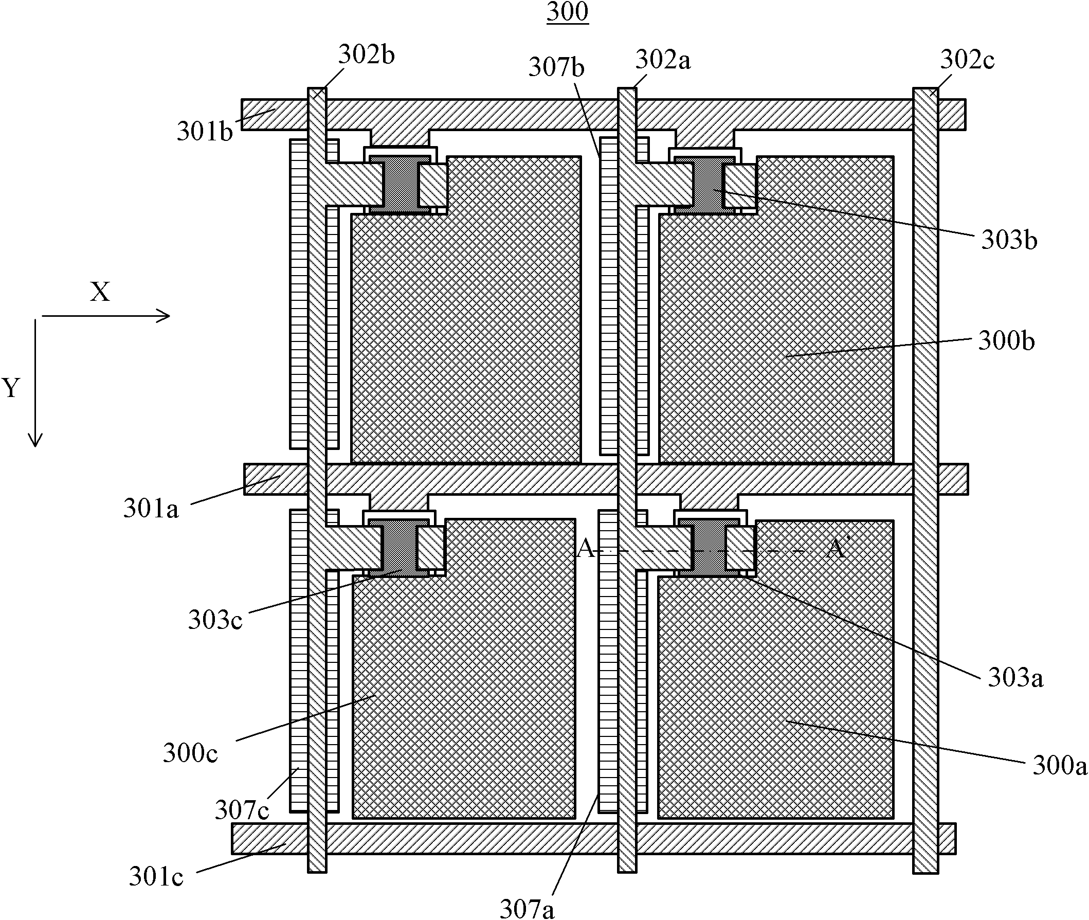
[0021] see figure 1 , figure 1 It is a partial schematic diagram of the flat display panel with the shielding line structure of the first embodiment of the present invention. The flat display panel includes a plurality of pixel electrodes and hundreds of scan lines, data lines and shielding lines. For the sake of simplification and convenience of illustration, only part of the flat display panel is shown in the following embodiments. ...


PUM


Abstract

The invention discloses a flat-panel display panel and a manufacturing method thereof. The flat-panel display panel comprises multiple rows of scanning lines, multiple columns of data lines and multiple parallel shielding lines superposed on the data lines. The multiple shielding lines are arranged on one sides of pixel electrodes in a one-to-one manner, and the multiple shielding lines and the multiple rows of scanning lines are made of the same metal. Because the shielding lines can increase shielding area, and the shielding lines and the scanning lines are made of the same metal, the shielding lines provided by the invention can shield more light rays to prevent the light rays from passing through two sides of the data lines under the condition of not increasing an additional process.

Description

【Technical field】 [0001] The present invention relates to a flat display panel and its forming method, in particular to a flat display panel with a shielding line structure and its forming method. 【Background technique】 [0002] Today's consumer electronic products generally use thin and light flat panel displays, among which liquid crystal displays have been widely used in various electronic devices such as televisions, mobile phones, personal digital assistants, digital cameras, computer screens or notebook computers. [0003] Thin film transistor liquid crystal display panels have gradually become the mainstream of the market due to their superior characteristics such as high image quality, good space utilization efficiency, low power consumption, and no radiation. In order to increase the surface brightness of the liquid crystal display panel and improve the utilization rate of the brightness of the light source, it is necessary to increase the light transmittance of the...

Claims


Application Information

Patent Timeline
Patent Type & Authority Applications(China)
IPC IPC(8): G02F1/1362G02F1/1368H01L21/77
CPCG02F1/1362H01L21/77H01L27/1288G02F1/136286G02F2001/136218G02F1/1368H01L27/124G02F1/136218
Inventor 陈世烽施明宏何海英
Owner SHENZHEN CHINA STAR OPTOELECTRONICS TECH CO LTD
Learn More