Punched roof awning frame with eaves

A technology for eaves and awnings, applied in tents/canopies, building types, buildings, etc., can solve the problems of tarpaulins being easily damaged, and the awning area of ​​tarpaulins is small.

Active Publication Date: 2016-06-01
XIAMEN ROADZUP OUTDOOR PROD
View PDF9 Cites 1 Cited by
  • Summary
  • Abstract
  • Description
  • Claims
  • Application Information

AI Technical Summary

Problems solved by technology

[0005] The existing roof-top awning frame has the following disadvantages: 1. The sun-shading area of ​​the tarpaulin is small; 2. The tarpaulin is braced on the top of the middle pole and the top seat, which is a point support, and the tarpaulin is easily broken.

Method used


Image

  • Punched roof awning frame with eaves
  • Punched roof awning frame with eaves
  • Punched roof awning frame with eaves

Examples


Embodiment 1

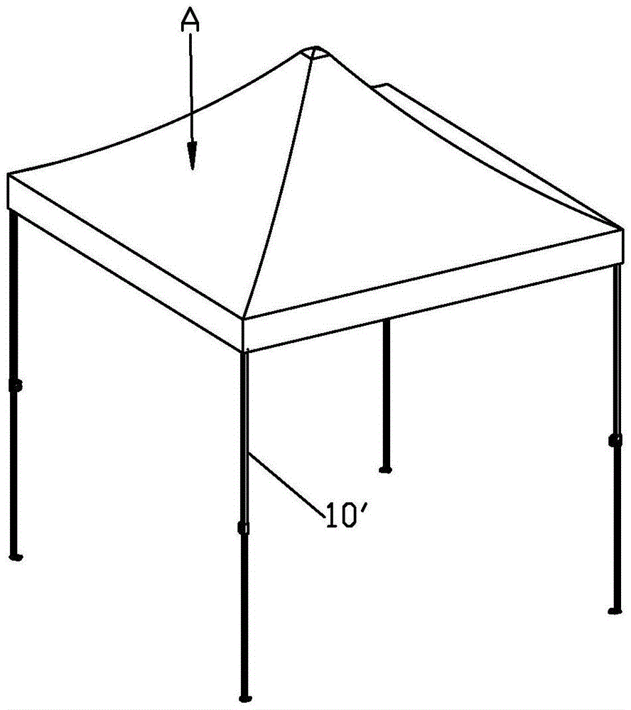
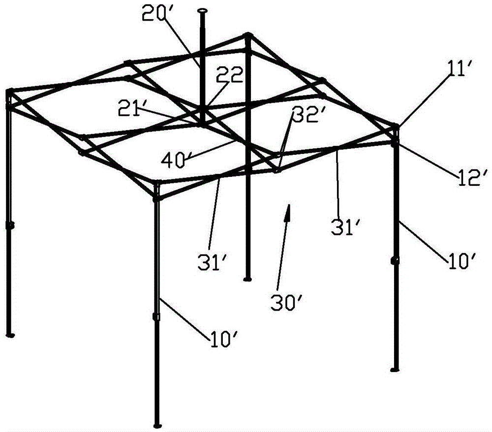
[0040] Please refer to the diagram Figure 4 to Figure 8 , a dome awning with an eave frame, including a dome awning frame and tarpaulin A. The roof awning frame includes at least three uprights 10 and at least one middle pole 20 , the uprights 10 can be telescopic uprights as required, and the at least three uprights 10 are arranged at the corners of the polygon surrounding the middle pole 20 . In this embodiment, four columns are taken as an example, but it is not limited to this, and three columns, six columns, eight columns, etc. can also be used as required. In this embodiment, one middle rod 20 is taken as an example, but it is not limited thereto. According to needs, two middle rods 20 may also be included, as in the second embodiment. Wherein, when there is only one middle pole 20, the second scissor frame is all established between all folding frames and the middle pole, and when there are two or three middle poles 20, then each middle pole and at least two of the co...

Embodiment 2

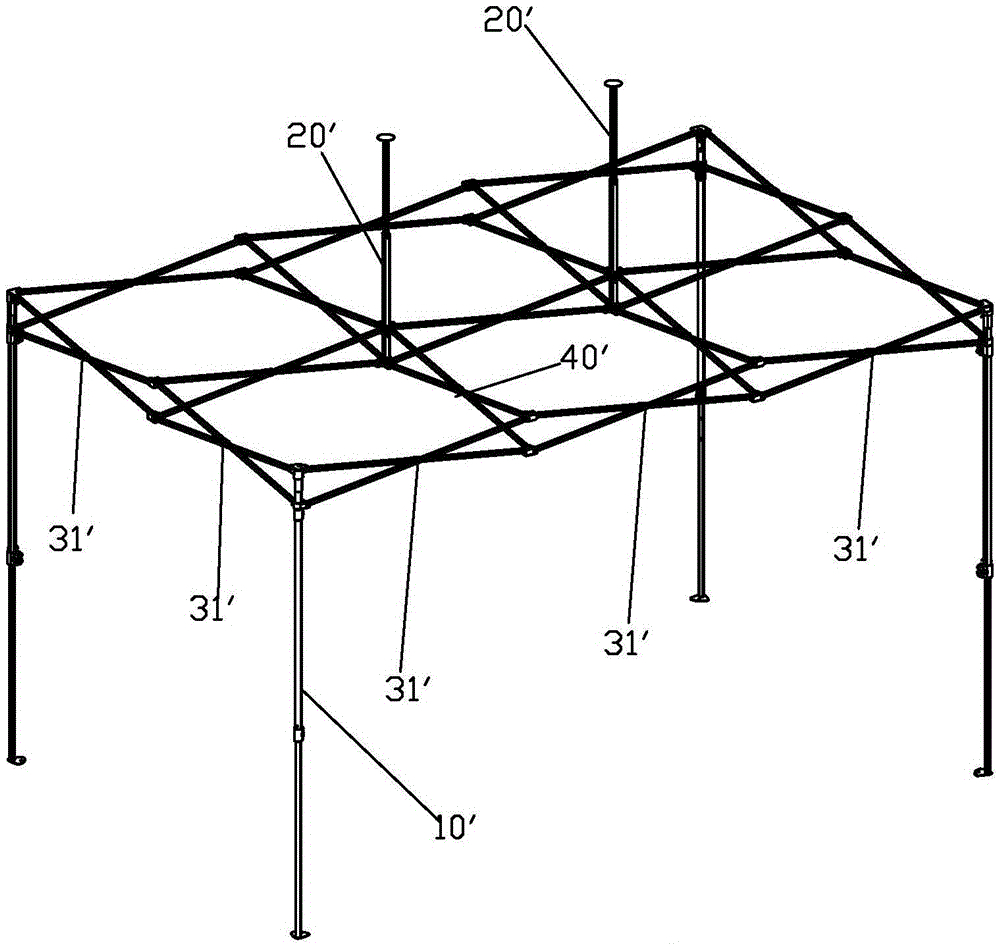
[0051] Please check Figure 9 , it differs from Example 1 in that:

[0052] The roof awning frame includes two middle poles 20; at least one third scissor frame 60 is pivotally connected between the second sliding seat and the base of the two middle poles 20, and the third scissor frame 60 may not be established as required; among the four folding frames The folding frame 30 facing two sides comprises three first scissor frames 31 connected in series, the folding frame 30 has four pivot joints, a second scissor frame is set between the middle bar and the two pivot joints, and the other Another second scissors frame is set between a middle rod and the other two pivots; the other two facing folding frames 30 include two first scissors frames 31 connected in series, the folding frame 30 has two pivots, the A second scissor frame is respectively arranged between the two pivot joints and the two middle rods. Make the entire roof-top awning frame look down and project into a recta...

Embodiment 3

[0054] Please check Figure 10 and Figure 11 , it differs from Embodiment 1 in that: the eave rod 53 is slidably connected to the corner push rod 51 and can extend out of the corner push rod 51 . In a preferred solution, the eave rod 53 is slidably connected in the hollow hole of the corner ram to form a telescopic tube, but it is not limited thereto, as required, it can also be connected to the outer surface of the corner ram to form a sliding connection relationship.


PUM


Abstract

The invention provides a top punching awning frame with an eave frame. The top punching awning frame comprises upright posts and a middle rod, wherein folding frames are arranged between every two adjacent upright posts, each folding frame comprises at least two first scissor frames in serial pivoting connection, and second scissor frames are respectively arranged on at least two pivoting parts of each folding frame, and between a base and a second slide seat of the middle rod. The upright posts are provided with an eave frame, the eave frame comprises an angle top rod, a support rod, and an eave rod, one end of the angle top rod is pivoted on top seats of the upright posts, one end of the support rod is pivoted on a first slide seat of the upright posts, the other end of the support rod is pivoted on the angle top rod, the angle top rod, the support rod, the upright posts and the first slide seat form a connecting rod mechanism, and the eave rod is movably connected with the connecting rod mechanism and can extend out of the upright posts when the awning frame is in an unfolded state. The top punching awning frame has the following advantages that the sun shielding area is increased, partial point supporting is at least changed into line supporting, the supporting stability of awning cloth is improved, the service life of the awning cloth is prolonged, and the support intensity and the stability of the awning frame are improved.

Description

technical field [0001] The invention relates to a roof awning frame with an eave frame. Background technique [0002] Existing roof awning frames, such as US5244001 published in the US patent database, and CN91105446.4 published in the Chinese patent database. [0003] Please check figure 1 , figure 2 , which respectively depict the first type of roof awning and roof awning frame. The roof awning includes a roof awning frame and a tarpaulin A', and the roof awning frame includes four columns 10' and a middle pole 20', and each column 10' is provided with a top seat 11' fixed on the top and a slide The middle rod 20' is provided with a base 21' fixed at the bottom end and a sliding second sliding seat 22'. The four columns 10' are surrounded by the middle pole 20', and a folding frame 30' is provided between the top seat 11' and the first sliding seat 12' of each adjacent two columns 10', and each adjacent two columns refers to the enclosing direction adjacent. The fol...

Claims


Application Information

Patent Timeline
Patent Type & Authority Patents(China)
IPC IPC(8): E04H15/44
Inventor 黄长久
Owner XIAMEN ROADZUP OUTDOOR PROD
Why Eureka
Try Eureka