
Water level monitoring system based on image processing and method

A technology for water level monitoring and image processing, applied in the field of image processing, can solve problems such as large environmental impact, personal safety of monitoring personnel, and inability to guarantee data accuracy.

Inactive Publication Date: 2013-09-25
XIDIAN UNIV
View PDF3 Cites 3 Cited by
  • Summary
  • Abstract
  • Description
  • Claims
  • Application Information

AI Technical Summary

Problems solved by technology

Float-type water level gauge is the most commonly used type, suitable for still water wells and water diversion channels, but after a period of operation, it is easy to form false water level and dead water level; The pressure generates a corresponding current to measure the height of the water level. The disadvantage is that the accuracy is relatively affected by the external environment and sediment, and it is not easy to popularize; the gas-mediated or liquid-mediated ultrasonic water level gauge uses ultrasonic waves to propagate in the air medium, and measures the transmission of sound waves. The method of measuring the water level at the receiving time interval, this kind of device is relatively affected by the environment, and the error is large
In addition, these methods do not have the ability of real-time remote monitoring, requiring manual on-site monitoring, and the cost is relatively high
[0003] At present, most water level monitoring stations in China still use the method of manual monitoring of water level. This method not only has the personal safety of the monitoring personnel, but also the accuracy of the data cannot be guaranteed. In addition, this method cannot be monitored in real time.

Method used


Image

  • Water level monitoring system based on image processing and method
  • Water level monitoring system based on image processing and method
  • Water level monitoring system based on image processing and method

Examples


Embodiment Construction

[0055] In order to make the technical solution of the present invention clearer, the present invention will be further described in detail below in conjunction with the accompanying drawings.

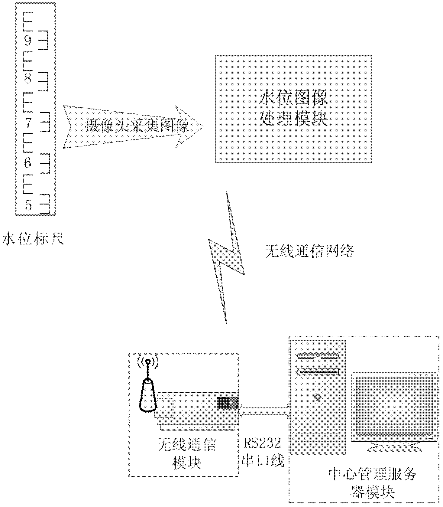
[0056] refer to figure 1 , the water level monitoring system based on image processing in the present invention includes a water level scale, a water level image processing module, a wireless communication module and a central management server module; wherein the image processing module sends data to the wireless communication module through a wireless communication network, and the wireless communication module and the central management The server modules are connected through RS232 serial cable.

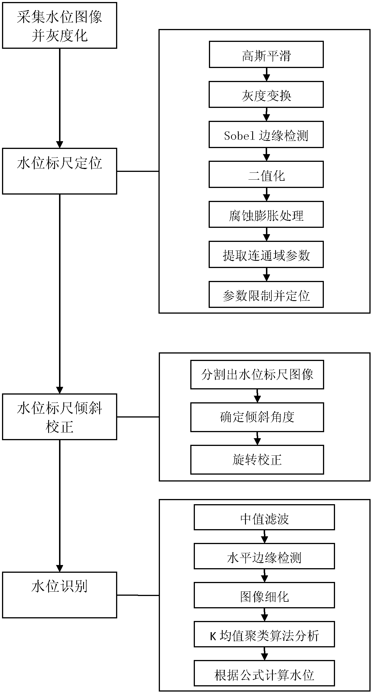
[0057] The water level image processing module includes a water level scale positioning submodule, a water level scale correction submodule, and a water level identification submodule.

[0058]The central management server module includes a database submodule, a water level drawing submod...


PUM


Abstract

The invention discloses a water level monitoring system based on image processing and a method, which mainly solve the problem that water level cannot be monitored automatically in the prior art. The water level monitoring system comprises a water level gauge, a water level image processing module, a wireless communication module and a central management server module. Working principle of the system is that: firstly the water level gauge is used for marking the water level, water level images marked by the water level gauge can be collected by a camera, the water level image processing module further performs automatic positioning, skew correcting and recognizing on the water level gauge in the water level images to obtain water level data and transmits the water level data to the wireless communication module through a wireless communication network, then the wireless communication module transmits the received water level data to the central management server module which stores the received water level data into a computer data base so as to draw current hydrograph in real time, when the current water level is higher than a preset water level, alarm information can be given out, and accordingly automatic monitoring of the water level can be achieved.

Description

technical field [0001] The invention belongs to the field of image processing technology, uses the image processing technology to automatically detect the water level and implements remote monitoring, and provides a new remote real-time monitoring technology for the water regime monitoring and water level of rivers and lakes in remote areas of my country, especially under harsh conditions in mountainous areas . Background technique [0002] At present, water security and water resource issues have become an important factor in my country's social and economic development. Safety issues, especially accidents caused by natural disasters such as floods, are extremely harmful. Therefore, it is very important to study real-time monitoring and early warning systems for water levels. . There are many methods of water level monitoring and detection. The self-recording water level gauge is commonly used in the world. In terms of the way it senses the water level, it can be divided int...

Claims


Application Information

Patent Timeline
Patent Type & Authority Patents(China)
IPC IPC(8): G01F23/22G06T5/00
Inventor 卢朝阳李静姜兵汪文芳李乔
Owner XIDIAN UNIV
Learn More