Combustion device for rotational flow mixed combustion by spraying air above uniformly distributed gas jets in loop

A technology of gas nozzles and combustion devices, which is applied in the directions of gas fuel burners, burners, combustion methods, etc., can solve the problems of polluting the environment, complex structure of combustion devices, and large combustion space.

Inactive Publication Date: 2012-06-13
ZHENGZHOU YUXING REFRACTORY MATERIAL
View PDF5 Cites 8 Cited by
  • Summary
  • Abstract
  • Description
  • Claims
  • Application Information

AI Technical Summary

Problems solved by technology

[0003] In view of the above situation, in order to overcome the defects of the prior art, the object of the present invention is to propose a combustion device in which the gas nozzles in the ring are evenly distributed on the spray air swirling mixed combustion, which can effectively solve the complex structure of many furnace combustion devices, or the need Large combustion space, and problems such as uneven gas mixing, insufficient combustion, environmental pollution, waste of energy, etc. (especially blast furnace hot blast stoves and kilns that mainly use heat)

Method used


Image

  • Combustion device for rotational flow mixed combustion by spraying air above uniformly distributed gas jets in loop
  • Combustion device for rotational flow mixed combustion by spraying air above uniformly distributed gas jets in loop
  • Combustion device for rotational flow mixed combustion by spraying air above uniformly distributed gas jets in loop

Examples


Embodiment Construction

[0008] The specific implementation manners of the present invention will be described in detail below in conjunction with the accompanying drawings.

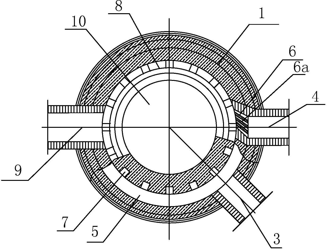
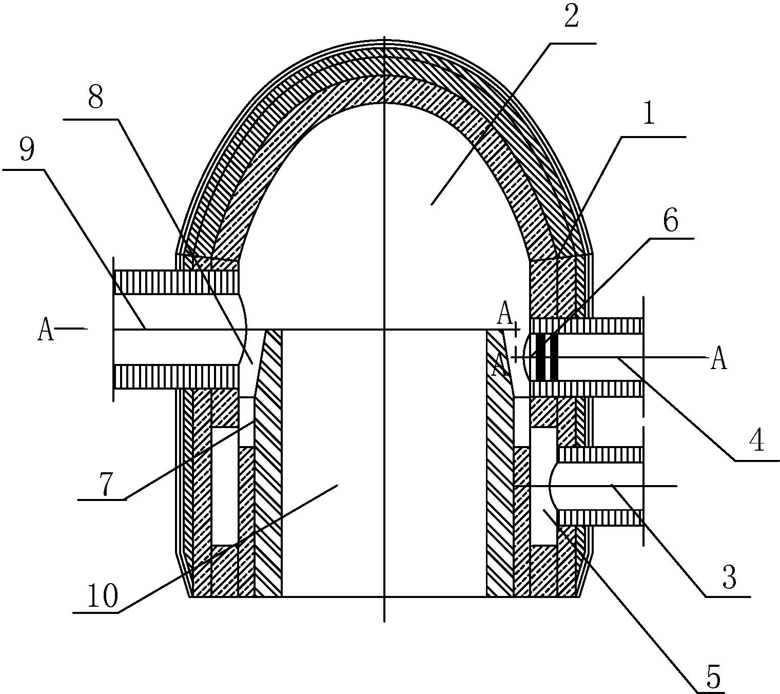
[0009] Such as figure 1 , 2 As shown, the present invention consists of a combustion chamber wall 1, a swirl and return combustion chamber 2, a gas intake pipe 3, an air intake pipe 4, a gas distribution loop 5, an air intake nozzle 6, a gas nozzle 7, and an air mixing loop 8. The airflow outlet 9 and the combustion device outlet section 10 are formed. The combustion chamber wall 1 is composed of a spherical vault and a cylinder. The upper space in the combustion chamber wall is a swirl and return combustion chamber 2. The combustion chamber wall On the cylindrical body of the body 1, a gas inlet pipe 3 and an air inlet pipe 4 are arranged perpendicular to its axis, the gas inlet pipe is placed on the lower side of the air inlet pipe, and the gas inlet pipe 3 is vertically or connected to the combustion chamber wall at an incli...


PUM


Abstract

The invention relates to a combustion device for rotational flow mixed combustion by spraying air above uniformly distributed gas jets in a loop. The problems that a combustion device has a complex structure and requires a larger combustion space, gas mixing is non-uniform, the combustion is incomplete, the environment is polluted and the energy is wasted are effectively solved. The upper part inside a wall body of a combustion chamber is provided with a rotational flow and backflow combustion chamber; a gas inlet pipe and an air inlet pipe are arranged on a cylinder; the gas inlet pipe is connected with a gas distributing loop; the gas jets on the upper part of the gas distributing loop are connected with an airflow mixing loop; the airflow mixing loop is positioned at the bottom of the rotational flow and backflow combustion chamber; the air inlet pipe is connected with the airflow mixing loop through an air inlet jet; a guide baffle is arranged in the air inlet jet; an airflow outlet is formed in the wall body of the combustion chamber or in the top of a spherical arch; and the lower part of the rotational flow and backflow combustion chamber is provided with an outlet section of the combustion device. Key problems of unstable combustion, low combustion intensity, low combustion temperature and the like of low-heat value gas are effectively solved, and the combustion device is low in manufacturing cost and has a simple structure.

Description

technical field [0001] The invention relates to a combustion device for blast furnace hot blast stove and other industrial kilns, in which the gas nozzles in the ring are uniformly distributed and sprayed with air swirling mixed combustion. Background technique [0002] At present, blast furnace hot blast stoves and other industrial furnaces are required to obtain high performance and high benefits under the combustion of low calorific value blast furnace gas from the perspective of energy saving and consumption reduction, and finally achieve the goals of high efficiency, energy saving, environmental protection, and increased production. For this reason, an efficient and enhanced combustion process is very necessary, which relates to the performance of the combustion device. Throughout the various gas combustion devices currently in use, they are mainly based on the mixing, preheating and ignition of gas and air in the combustion space. This mode always has uneven mixing, in...

Claims


Application Information

Patent Timeline
IPC IPC(8): F23D14/24F23D14/46F23D14/70
Inventor 陈维汉刘辉凯
Owner ZHENGZHOU YUXING REFRACTORY MATERIAL
Why Eureka
Try Eureka