Main control circuit for electrocardiograph recording meter

A main control circuit and recorder technology, applied in the field of circuits, can solve the problems of slow program running speed, low security, leakage of storage content, etc., and achieve the effects of increased running speed, wide input voltage, and high security

Inactive Publication Date: 2012-06-06
葛飞
View PDF0 Cites 1 Cited by
  • Summary
  • Abstract
  • Description
  • Claims
  • Application Information

AI Technical Summary

Problems solved by technology

[0002] Currently, large-scale electrocardiographs are mainly used for the examination of patients with heart disease. Patients must go to the hospital to do this examination. However, some patients have a sudden attack and cannot go to the hospital in time. Work brings many inconveniences
The appearance of portable ECG recorder solves this problem, but this recorder has special requirements on power consumption and requires low power consumption, but the main control chip in the existing ECG recorder takes a long time from sleep to wake-up , the input voltage range is relatively narrow, not suitable for handheld devices, the program runs slowly, and the power consumption cannot meet the requirements
[0003] Although there are many kinds of software specially used for erasing data in the storage device at present, it needs to configure a computer during operation, resulting in waste of resources, inconvenient operation, low work efficiency, and when the storage device is connected to the computer, it is difficult for others It is easy to open the storage device, thereby revealing the storage content, and the security is low

Method used


Image

  • Main control circuit for electrocardiograph recording meter
  • Main control circuit for electrocardiograph recording meter

Examples


Embodiment Construction

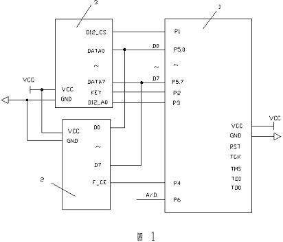
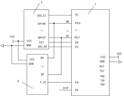
[0016] The present invention will now be described in further detail in conjunction with the accompanying drawings and preferred embodiments. These drawings are all simplified schematic diagrams, which only illustrate the basic structure of the present invention in a schematic manner, so they only show the configurations related to the present invention.

[0017] Such as figure 1 As shown, a main control circuit for an electrocardiogram recorder includes a main control chip 1, a USB chip 3, and a storage chip 2. The main control chip 1 is composed of a P1 port, a P2 port, a P3 port, a P4 port, a P5 port, P6 mouth is formed, and P1 mouth is connected with the pin of described USB chip 3 control signals; P2 mouth is connected with the KEY of described main control chip 1; P3 mouth is connected with the control pin of described USB chip 3; P4 mouth is connected with described memory chip 2 control signal pins; P5 port including P5.0-P5.7 pins are connected to the data terminals ...


PUM


Abstract

The invention relates to a main control circuit for an electrocardiograph recording meter, which comprises a main control chip, a USB chip and a storage chip, wherein a port P1 is connected with a control signal pin of the USB chip; a port P2 is connected with a KEY of the main control chip; a port P3 is connected with a control pin of the USB chip; a port P4 is connected with a control signal pin of the storage chip; a port P5 comprises pins P5.0-P5.7 and is connected with data ends of the storage chip and the USB chip through eight data buses D0-D7; a port P6 is an AD channel and is used for carrying out analog-to-digital conversion; and a destruction module is arranged between the main control chip and a self-destruction key. The invention has multiple low-power-consumption modes, and the dormancy-to-wakening time is less than 5ms, thereby enhancing the program operating speed and lowering the power consumption; the structure also has the self-destruction function: the user only needs to press the self-destruction key, and data in need of deletion in the storage chip can be automatically destructed without external software or destruction equipment; and thus, the invention is convenient to use, and has the advantage of high safety.

Description

technical field [0001] The invention relates to a circuit, in particular to a main control circuit used for self-destruction of an electrocardiogram recorder. Background technique [0002] Currently, large-scale electrocardiographs are mainly used for the examination of patients with heart disease. Patients must go to the hospital to do this examination. However, some patients have a sudden attack and cannot go to the hospital in time. Work brings many inconveniences. The appearance of portable ECG recorder solves this problem, but this recorder has special requirements on power consumption and requires low power consumption, but the main control chip in the existing ECG recorder takes a long time from sleep to wake-up , the input voltage range is relatively narrow, it is not suitable for handheld devices, the program runs slowly, and the power consumption cannot meet the requirements. [0003] Although there are many kinds of software specially used for erasing data in th...

Claims


Application Information

Patent Timeline
IPC IPC(8): A61B5/0432
Inventor 葛飞
Owner 葛飞
Why Eureka
Try Eureka