
Sensor device

A sensor device and sensor unit technology, applied in the direction of measuring devices, electrical devices, instruments, etc., can solve the problem of mixing amplifiers into amplifiers, etc.

Active Publication Date: 2012-05-30
PANASONIC CORP
View PDF6 Cites 10 Cited by
  • Summary
  • Abstract
  • Description
  • Claims
  • Application Information

AI Technical Summary

Problems solved by technology

However, the output from the amplifier can be mixed with offset voltage and low frequency 1 / f noise inherent in the amplifier

Method used


Image

  • Sensor device
  • Sensor device
  • Sensor device

Examples


Embodiment Construction

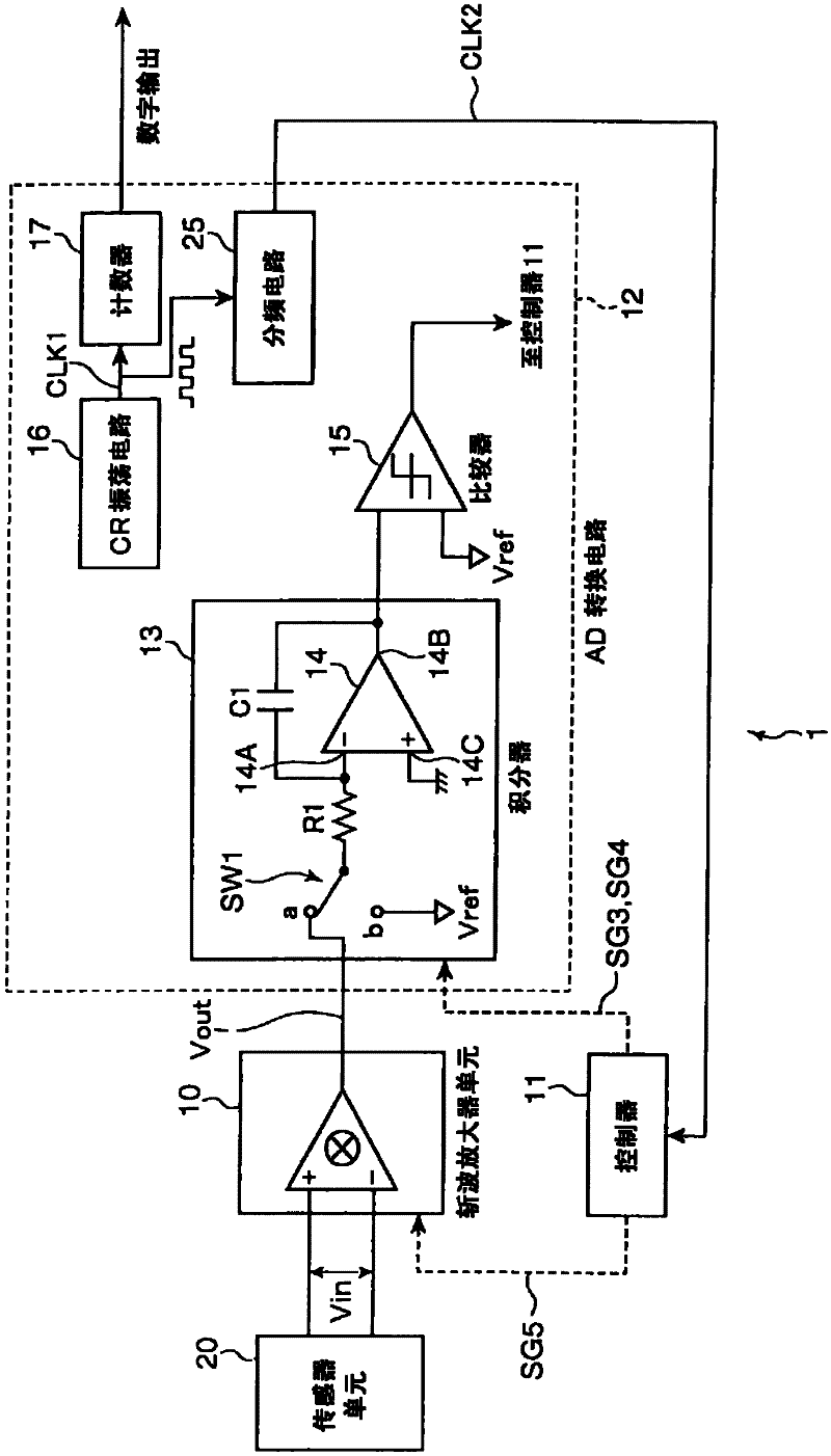
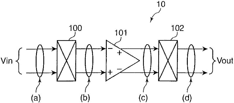
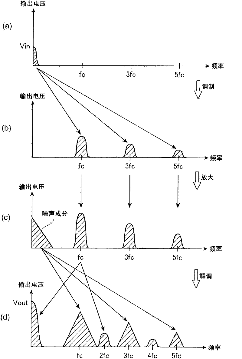
[0026] A sensor device according to an embodiment of the present invention will be described below. figure 1 is a diagram showing a typical configuration of a sensor device. figure 2 is a diagram showing a typical configuration of a chopper amplifier unit. image 3 A graph showing typical operation of a chopper amplifier unit is shown. Figure 4 is a diagram showing a typical construction of an integrator.

[0027] figure 1 The sensor device 1 shown in includes a controller (control unit) 11 . The controller 11 collectively controls the respective constituent elements described below. The sensor device 1 further includes a voltage detection type sensor unit 20 , a chopper amplifier unit 10 , and an AD conversion circuit (digital conversion unit) 12 . The sensor unit 20 converts a physical quantity into a voltage value, and outputs a voltage signal representing the voltage value.

[0028] The chopper amplifier unit 10 includes a first chopper circuit 100 , an operational...


PUM


Abstract

A sensor device is provided with a voltage detection type sensor unit (20) for converting a physical quantity into a voltage value and outputting a voltage signal indicating the voltage value; a chopper amplifier unit (10) for generating a modulation signal by chopping the voltage signal output from the sensor unit with a predetermined chopping frequency, amplifying the modulation signal into an amplification signal, then demodulating the amplification signal and outputting it as an output signal; an integration unit (13) including an operational amplifier (14) for amplifying a voltage difference between a voltage at a non-inverting input terminal and a voltage at an inverting input terminal, an input resistor (R1) connected to the inverting input terminal of the operational amplifier and a capacitor (C1) connected between the inverting input terminal and an output terminal of the operational amplifier (14) and adapted to sample the output signal output from the chopper amplifier unit (10) at a predetermined sampling frequency and integrate the sampled output signal; and a digital conversion unit for converting the output signal integrated by the integration unit into a digital signal.

Description

technical field [0001] The invention relates to a sensor device for detecting physical quantities. Background technique [0002] Conventionally, a sensor device having a sensor unit for converting a physical quantity into an electrical quantity is known. For example, the sensor unit is a thermocouple. Thermocouples measure the temperature of an object by absorbing infrared rays emitted from the object. [0003] Thermocouples represent temperature changes in the form of a voltage signal. For example, if the amount of temperature change is 1 degree, the amount of temperature change is expressed in the form of a voltage signal with a voltage value of 2.3 μV. [0004] Since the amount of temperature change is expressed in the form of a voltage signal of a small voltage value, the voltage signal needs to be amplified with a high gain in order to accurately measure the temperature of an object using the voltage signal. [0005] Accordingly, sensor devices traditionally include...

Claims


Application Information

Patent Timeline
Patent Type & Authority Applications(China)
IPC IPC(8): H03F3/393H03F3/45H03F3/387
CPCH03F2200/264H03F2203/45138H03F2200/261H03F3/393H03M1/52H03F3/45475H03M1/0663H03F3/387H03F2200/78G01K7/01
Inventor 刘俊豪熊原稔
Owner PANASONIC CORP
Learn More