Battery pack device
A technology for battery packs and equipment, which is applied to battery pack components, secondary batteries, large-sized batteries/battery packs, etc., and can solve the problems of not providing cooling fans and narrowing air passages
- Summary
- Abstract
- Description
- Claims
- Application Information
AI Technical Summary
Problems solved by technology
Method used
Image

Examples
no. 1 example
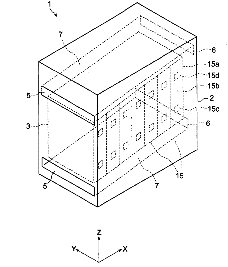
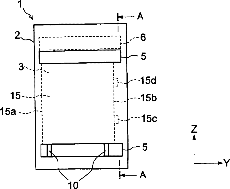
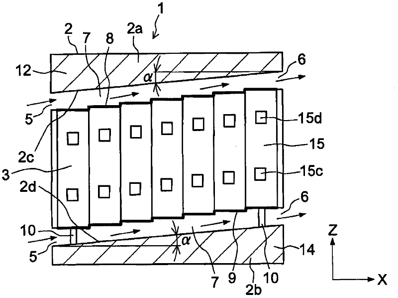
[0026] Such as Figure 1 to Figure 3 As shown, the battery pack device 1 according to this embodiment is a stationary type battery pack device used in general houses, factories, and the like. Specifically, the battery pack device 1 includes a casing 2, a battery module 3, an air inlet 5, an air outlet 6, an air passage (air passage) 7, an upper end fixing device 8, a lower end fixing device 9, a support 10 and a control part storage equipment 12,14.
[0027] In the battery module 3, a plurality of battery cells 15 stacked on each other such as Figure 1 to Figure 3 arrangement shown. Such as Figure 4 As shown, each battery cell 15 is formed in a substantially rectangular parallelepiped shape (thin rectangular box shape). Each battery cell 15 has a pair of terminals 15c, 15d protruding from the end face 15b of the battery cell body 15a. Each battery unit 15 is a storage battery, for example, a lithium-ion battery, a nickel-metal hydride battery, or the like.
[0028] Suc...
no. 2 example
[0041] Next, the Figure 8 with Figure 9 The second embodiment will be described. Note that in Figure 8 with Figure 9 , are marked with the same reference numerals and symbols as the Figure 1 to Figure 3 The constituent elements are the same as those of the first embodiment shown in , and description thereof will be omitted. The second embodiment is constructed by making changes to the first embodiment, and only the changed structure will be described. In addition, in Figure 8 with Figure 9 , omitting the pair figure 2 with image 3 Description of strut 10 shown in .
[0042] Specifically, as Figure 8 with Figure 9 As shown, in the battery pack device 31 , a plurality of battery modules 3 arranged side by side in the vertical direction (Z direction, which is the width direction of the battery cells) are accommodated in the case. Furthermore, in the battery pack device 31, the air passage 7 is also provided between the battery modules 3 in the case. Theref...
no. 3 example
[0044] Next, the Figure 10 to Figure 12 A third embodiment is described. Note that in Figure 10 to Figure 12 , are marked with the same reference numerals and symbols as the Figure 1 to Figure 3 , Figure 8 with Figure 9 The constituent elements of the first embodiment and the second embodiment shown in are the same, and descriptions thereof will be omitted. Note that in Figure 10 with Figure 12 , omitting the pair figure 2 with image 3 Description of strut 10 shown in .
[0045] Such as Figure 10 with Figure 11 As shown, in addition to the structure of the battery pack device 1 according to the first embodiment, the battery pack device 41 also includes a plurality of air passages (second air passages) 47, which are provided by the battery cells 15 in the battery module 43. Formed by gaps in the shape of gaps between them. These air passages 47 form an air flow passing between the battery cells 15 in the case 2 in the vertical direction (Z direction, whic...
PUM
 Abstract
Description
Claims
Application Information
 - R&D
- Intellectual Property
- Life Sciences
- Materials
- Tech Scout
- Unparalleled Data Quality
- Higher Quality Content
- 60% Fewer Hallucinations
Browse by: Latest US Patents, China's latest patents, Technical Efficacy Thesaurus, Application Domain, Technology Topic, Popular Technical Reports.
© 2025 PatSnap. All rights reserved.Legal|Privacy policy|Modern Slavery Act Transparency Statement|Sitemap|About US| Contact US: help@patsnap.com