


Quick Research
Generate reliable direction feasibility study reports for your R&D in just a few steps.

Technical Q&A
Discover and master advanced knowledge NOW. Basics, ideas, possibilities, all at once.

Find Solutions
As an expert in R&D theories, this can generate solutions to your technical problems instantly.

Evaluate Feasibility
Analyze your overall solution with one click, know your potential R&D risks in advance.

Monitor Landscape
Get weekly tech updates, stay abreast of the latest tech innovations and key insights.
Light source device and projector
A technology of a light source device and a light source unit, which is applied to projection devices, lighting devices, components of lighting devices, etc., and can solve problems such as difficulty in obtaining light quantity and increasing the light quantity of excitation light
- Summary
- Abstract
- Description
- Claims
- Application Information
AI Technical Summary
Problems solved by technology
Method used
Image

Examples
no. 1 Embodiment approach
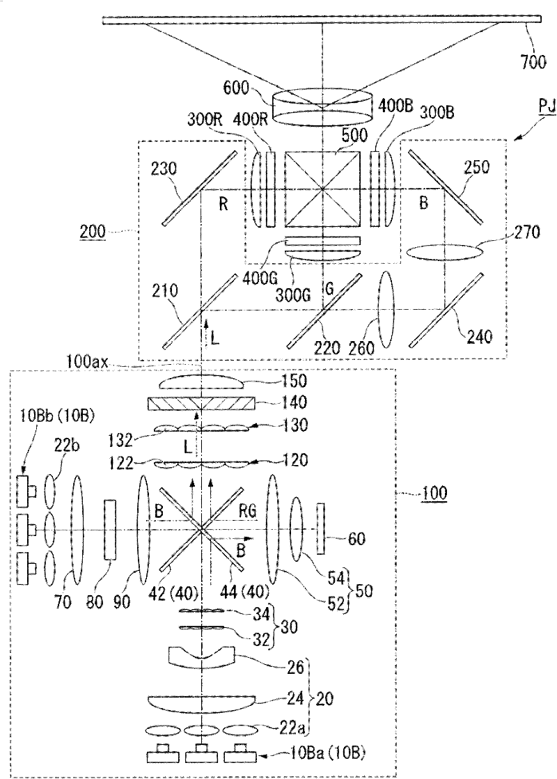
[0052] Below, while referring to Figure 1 to Figure 13 , the light source device and the projector according to the first embodiment of the present invention will be described. In addition, in all the drawings below, in order to make the drawings easier to see, the dimensions and / or ratios of the components are appropriately different.
[0053] figure 1 It is a schematic diagram showing the light source device 100 and the projector PJ of the present embodiment. The projector PJ as shown in the drawing includes a light source device 100 , a color separation optical system 200 , a liquid crystal light valve (light modulation element) 400R, a liquid crystal light valve 400G, a liquid crystal light valve 400B, a color combining element 500 , and a projection optical system 600 .
[0054] The projector PJ operates as follows when summarized. The light emitted from the light source device 100 is separated into a plurality of color lights by the color separation optical system 20...
no. 2 Embodiment approach
[0143] Figure 14 It is an explanatory diagram of the light source device according to the second embodiment of the present invention. In the following description, the same reference numerals are attached to the same components as those of the first embodiment, and detailed descriptions are omitted.
[0144] as shown in Figure 14 Basically, the configuration of the light source device 104 is partially the same as that of the light source device 100 of the first embodiment. The difference is that the lens integrators are not paired and only one first lens array 32 is used. In the present embodiment, the superimposing optical system 50 functions as the condensing optical system of the present invention.
[0145] Figure 15 It is an explanatory diagram showing the functions of the first lens array 32 and the superimposing optical system 50 . exist Figure 15 In the above, for simplicity, the overlapping optical system 50 is schematically illustrated as one convex lens. T...
PUM
 Abstract
Description
Claims
Application Information
 - R&D Engineer
- R&D Manager
- IP Professional
- Industry Leading Data Capabilities
- Powerful AI technology
- Patent DNA Extraction
Browse by: Latest US Patents, China's latest patents, Technical Efficacy Thesaurus, Application Domain, Technology Topic, Popular Technical Reports.
© 2024 PatSnap. All rights reserved.Legal|Privacy policy|Modern Slavery Act Transparency Statement|Sitemap|About US| Contact US: help@patsnap.com