


Quick Research
Generate reliable direction feasibility study reports for your R&D in just a few steps.

Technical Q&A
Discover and master advanced knowledge NOW. Basics, ideas, possibilities, all at once.

Find Solutions
As an expert in R&D theories, this can generate solutions to your technical problems instantly.

Evaluate Feasibility
Analyze your overall solution with one click, know your potential R&D risks in advance.

Monitor Landscape
Get weekly tech updates, stay abreast of the latest tech innovations and key insights.
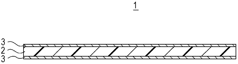
Heat resisting micro pore film and battery diaphragm
A microporous film, heat-resistant technology, applied in the field of battery separators, can solve problems such as internal short circuits, achieve the effect of increasing the number and maintaining heat resistance
- Summary
- Abstract
- Description
- Claims
- Application Information
AI Technical Summary
Problems solved by technology
Method used
Image

Examples
Embodiment 1
[0107] Polyvinylidene fluoride (PVdF) resin and N-methyl-2-pyrrolidone (NMP) each having a weight average molecular weight of 1,000,000 were mixed at a weight ratio of PVdF:NMP=10:90. Polyvinylidene fluoride was sufficiently dissolved in N-methyl-2-pyrrolidone, thereby preparing a polyvinylidene fluoride solution in which polyvinylidene fluoride was dissolved in an amount of 10% by weight.
[0108] A fine powder of alumina with an average particle size of 500 nm [Al 2 o 3 , Sumicorundum (registered trademark) AA-03, commercially available from Sumitomo Chemical Company, Limited] was added to the polyvinylidene fluoride solution as an inorganic material at 20 times the weight of polyvinylidene fluoride. The resultant was then stirred with a ball mill, thereby preparing a use slurry.
[0109] Next, the application slurry was applied to a substrate having a thickness of 12 μm as a polyethylene microporous membrane (commercially obtained from Tonen General Sekiyu K.K.) using a t...
Embodiment 2
[0115] The heat-resistant layers were individually formed on both faces of the substrate so that one heat-resistant layer had a thickness of 1.55 μm and the total heat-resistant layers had a thickness of 3.1 μm. A microporous membrane with a heat-resistant layer was produced in the same manner as employed in Example 1 except for such a process configuration.
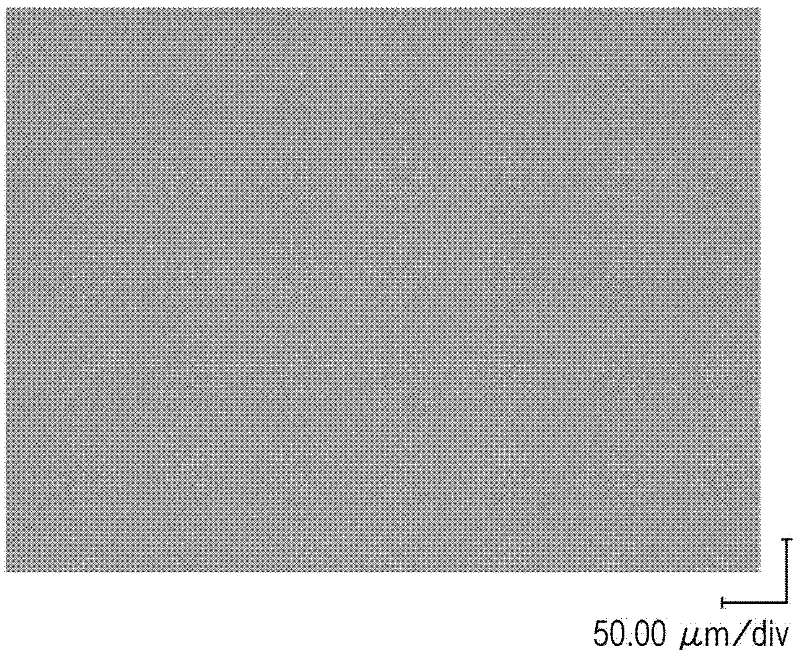
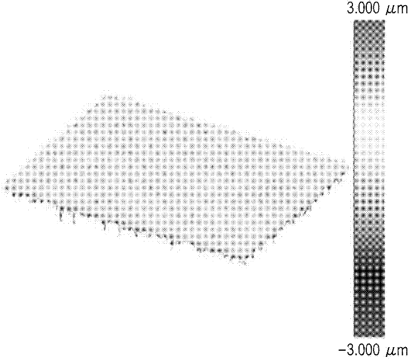
[0116] In the microporous membrane produced in this way, the total thickness of the heat-resistant layer was 6.2 times the average particle diameter of the heat-resistant particles contained in the heat-resistant layer. In addition, in the surface of the heat-resistant layer, it was found that the number of protrusions was 20.7 and the area was 46.1 μm 2 .
Embodiment 3
[0118] The heat-resistant layers were individually formed on both faces of the substrate so that the thickness of one heat-resistant layer was 2.75 μm and the total thickness of the heat-resistant layers was 5.5 μm. A microporous membrane with a heat-resistant layer was produced in the same manner as employed in Example 1 except for such a process configuration.
[0119] In the microporous membrane produced in this way, the total thickness of the heat-resistant layer was 11.0 times the average particle diameter of the heat-resistant particles contained in the heat-resistant layer. In addition, in the surface of the heat-resistant layer, it was found that the number of protrusions was 1.4 and the area was 1.0 μm 2 .
PUM
| Property | Measurement | Unit |
|---|---|---|
| melting point | aaaaa | aaaaa |
| particle size | aaaaa | aaaaa |
| thickness | aaaaa | aaaaa |
Abstract
Description
Claims
Application Information
 - R&D Engineer
- R&D Manager
- IP Professional
- Industry Leading Data Capabilities
- Powerful AI technology
- Patent DNA Extraction
Browse by: Latest US Patents, China's latest patents, Technical Efficacy Thesaurus, Application Domain, Technology Topic, Popular Technical Reports.
© 2024 PatSnap. All rights reserved.Legal|Privacy policy|Modern Slavery Act Transparency Statement|Sitemap|About US| Contact US: help@patsnap.com