
Fully automatic film sticking machine

A film laminating machine, fully automatic technology, applied in the direction of layered products, lamination devices, lamination, etc., can solve the problems of poor dimensional accuracy of film cutting, poor position accuracy of protective film, poor position accuracy of film sticking, etc. High-precision size, high-precision film position, and the effect of cutting film edges

Inactive Publication Date: 2012-05-23
SHENZHEN CEWAY TECH
View PDF0 Cites 35 Cited by
  • Summary
  • Abstract
  • Description
  • Claims
  • Application Information

AI Technical Summary

Problems solved by technology

[0003] Because the protective film is very thin and soft, it is generally difficult to achieve 100% cutting by die punching; if the protective film with a backing paper is used, although it is easy to cut, it is difficult to achieve the need to tear off the protective film to stick the film during the film sticking process. Automatic film tearing, so it is difficult to automate the application of protective film
At present, the industry basically uses manual sticking of protective film, and manual work has the following disadvantages: (1) low work efficiency; (2) poor positional accuracy of sticking protective film, which is difficult to guarantee for those with positional accuracy requirements; (3) high labor intensity , easy to fatigue the operator
However, some of the current market has adopted the automatic protective film technology. This technology uses die-cutting and cutting first and then pasting technology. This technology has the following defects: (1) The position accuracy of the film is poor. It cannot be realized; (2) The reliability is not good, and 100% film cutting and filming cannot be realized; (3) The dimensional accuracy of cutting film is poor, and it cannot meet the high-precision requirements; (4) It is not compatible with various product filming

Method used


Image

  • Fully automatic film sticking machine
  • Fully automatic film sticking machine
  • Fully automatic film sticking machine

Examples


Embodiment Construction

[0033] In order to express the present invention more clearly, the present invention will be further described below in conjunction with the accompanying drawings.

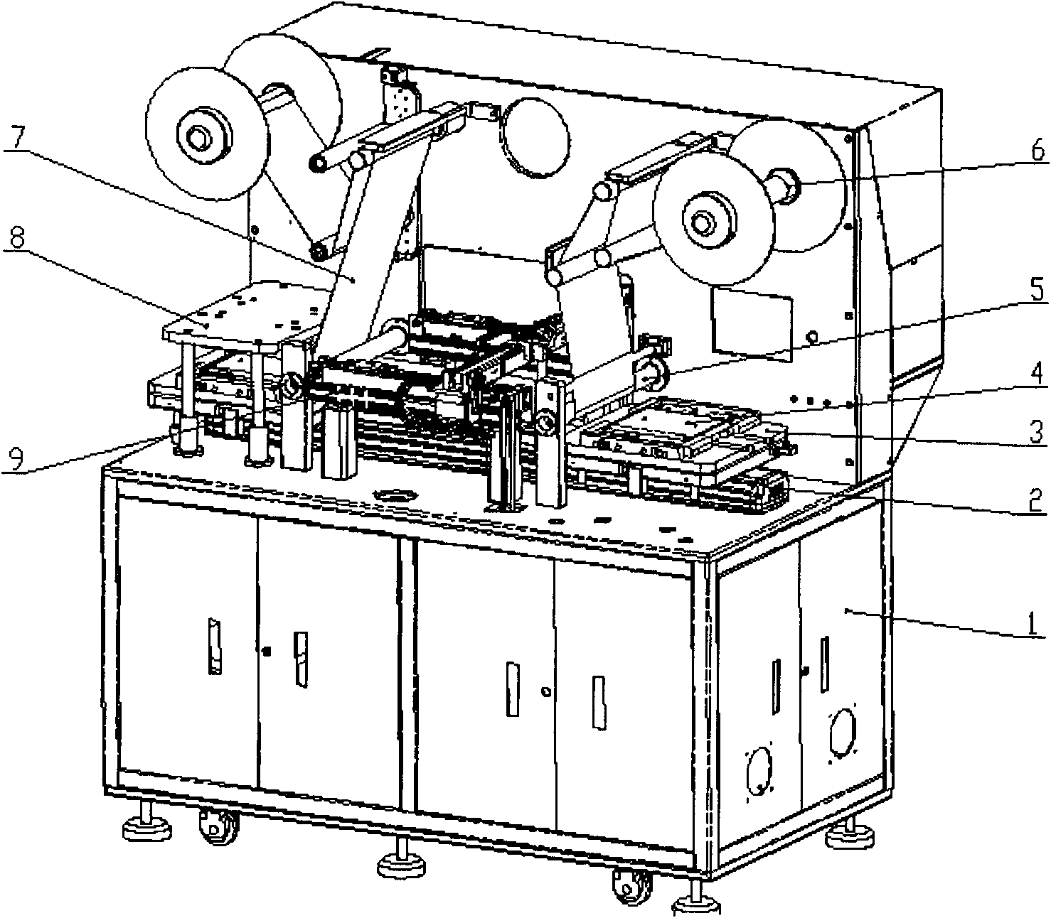
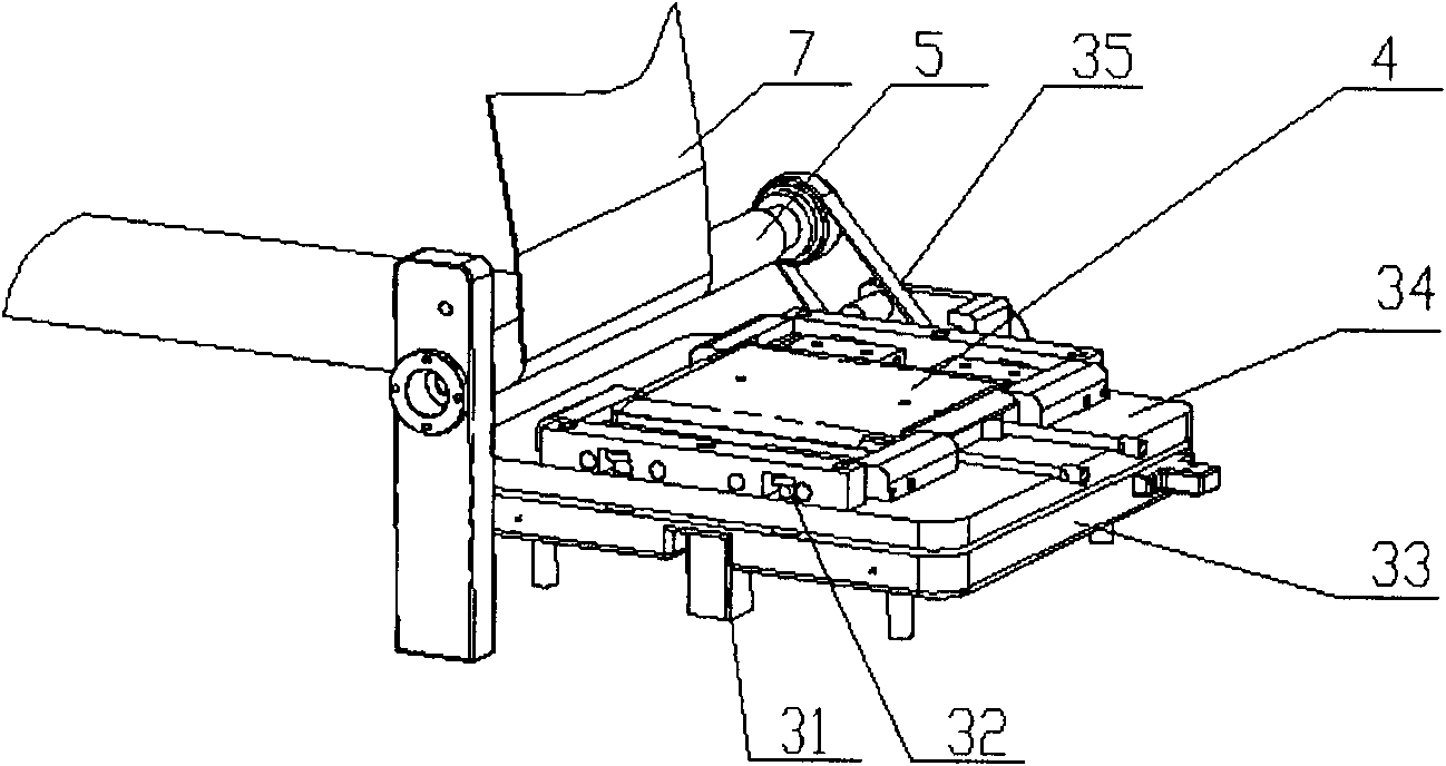
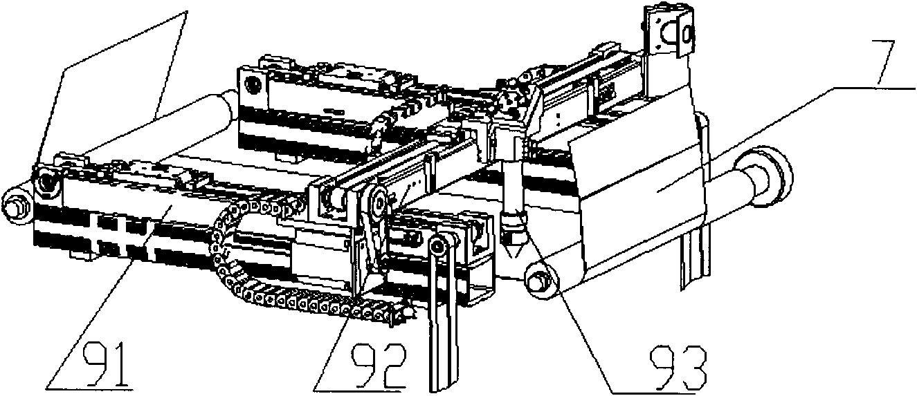
[0034] like figure 1 As shown, the present invention provides a fully automatic film laminating machine, including a body 1 and a transmission system 2 placed on the body 1, a product carrier 3, a pressure roller 5, a film cutting system 9, a film pressing system 8, and a film feeding system 6 And the control system placed in the body 1. The pasted product 4 is placed on the product carrier 3, and the product carrier 3 is fixed on the transmission system 2. The transmission system 2 is driven by a ball screw and a servo motor, and is driven by a control system to achieve precise positioning. The transmission system 2 drives the product carrier 3, and drives the pasted product 4 to move forward. When passing the pressure roller 5, the pressure roller 5 presses the protective film 7 onto the surface of the pasted p...


PUM


Abstract

The invention relates to a fully automatic film sticking machine, which comprises a machine body, a transmission system, a film cutting system, a film press system, a product carrier system, a press roller, a film conveying system and a control system, wherein the transmission system, the film cutting system and the film press system are arranged on the machine body, the product carrier system is arranged on the transmission system, the press roller is arranged on the product carrier system, the film conveying system is arranged on the machine body and is connected with the product carrier system, the film cutting system is connected with the product carrier system, and the control system is arranged in the machine body. The fully automatic film sticking machine has the advantages that the automatic film sticking, the automatic film conveying and the automatic cutting are realized, the automatic film sticking position precision and film cutting dimension precision are high, and in addition, the fully automatic film sticking machine can be compatible with different film sheet thicknesses and can be used for film sticking for products in different shapes.

Description

technical field [0001] The invention relates to a film sticking device, in particular to a film sticking device in the field of electronics and electrical appliances, and more specifically to a fully automatic film sticking machine. Background technique [0002] At present, the competition of consumer products in the electronics and electrical appliances industry is very fierce. In order to occupy the market and realize product value, the appearance of the product has become an important factor. Since the product shell parts may come into contact with external objects during production, processing and assembly, as well as product inspection and handling, it may cause slight scratches, scratches, dirt and other defects on the surface, which will affect the appearance quality of the product. Therefore, it has become a necessary link to protect the surface of the product shell parts, and the surface protection film is a commonly used protection process. [0003] Because the pr...

Claims


Application Information

Patent Timeline
Patent Type & Authority Applications(China)
IPC IPC(8): B32B37/00
Inventor 聂林红陈远开何立强
Owner SHENZHEN CEWAY TECH
Learn More