Borehole compensated resistivity logging tool having an asymmetric antenna spacing

A resistivity, logging-while-drilling technology, which is applied in electrical/magnetic detection for logging records, borehole/well components, and electromagnetic wave detection, etc., can solve problems such as calibration errors, achieve accurate drilling compensation, The effect of total tool length reduction

Inactive Publication Date: 2012-05-16
PRAD RES & DEV LTD
View PDF3 Cites 11 Cited by
  • Summary
  • Abstract
  • Description
  • Claims
  • Application Information

AI Technical Summary

Problems solved by technology

While this solution overcomes the above problems, it requires the calibration transmitter to be positioned precisely between the receivers
Any error in position (or deformation of the tool body due to extreme drilling temperatures and pressures) can result in significant calibration errors

Method used


Image

  • Borehole compensated resistivity logging tool having an asymmetric antenna spacing
  • Borehole compensated resistivity logging tool having an asymmetric antenna spacing
  • Borehole compensated resistivity logging tool having an asymmetric antenna spacing

Examples


Embodiment Construction

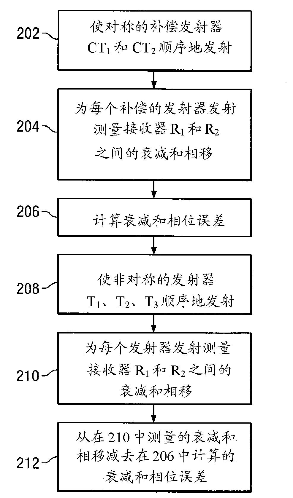
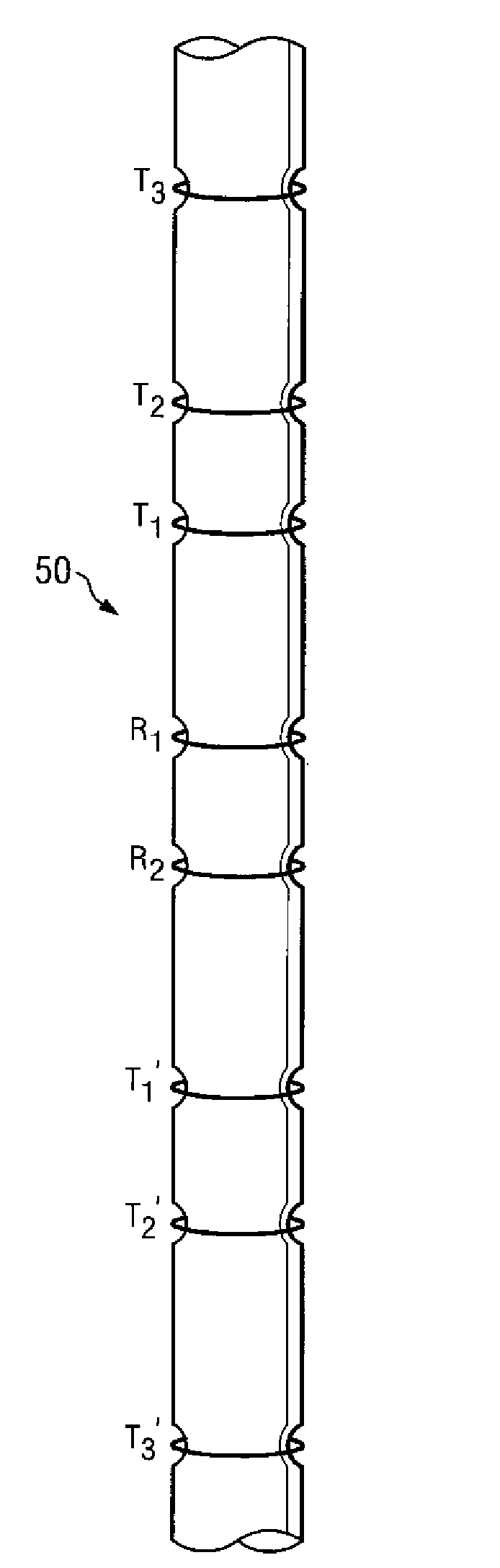
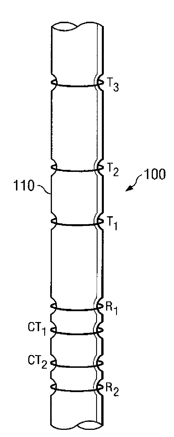
[0019] figure 2 An exemplary embodiment of a LWD resistivity tool 100 according to the present invention is shown. The resistivity tool 100 includes a plurality of spaced apart transmitters T disposed about a tool body 110 1 , T 2 and T 3 and a pair of spaced receivers R 1 and R 2 . Transmitter T 1 , T 2 and T 3 can be considered asymmetric since they are deployed on the receiver pair R 1 and R 2 on one axial side of and since there is no corresponding symmetrical transmitter deployed on the opposite axial side of the receiver. In contrast to the prior art resistivity tool 50 shown in FIG. 1, the present invention does not include a second set of symmetrical emitters. The resistivity tool 100 also includes a pair of symmetrical compensation transmitters CT 1 and CT 2 . exist figure 2 In the exemplary embodiment shown, these compensating transmitters CT 1 and CT 2 Axially deployed on the receiver pair R 1 and R 2 between. Although the invention is not limite...


PUM


Abstract

A compensated resistivity logging while drilling tool (100,12) having axially asymmetrically spaced transmitters (T1,T2,T3) is configured to provide compensated resistivity measurements. In one exemplary embodiment, the tool (100,120) includes first and second compensating transmitters (CT1,CT2), preferably deployed axially symmetrically between first and second spaced receivers (R1,R2). The tool (100,120) further includes a plurality of transmitters(T1,T2,T3) deployed axially asymmetrically with respect to the receivers (R1,R2), e.g., on one axial side of the receivers (R1,R2). The compensating transmitters (CT1,CT2) are configured to acquire a borehole compensation that may be subtracted from conventional phase and attenuation measurements.

Description

technical field [0001] The present invention relates generally to measurement tools for use while drilling wells for measuring electromagnetic properties of subterranean wells. More specifically, the present invention relates to well compensated resistivity logging tools having asymmetric emitter spacing along the tool longitudinal axis. Background technique [0002] The use of electrical measurements in prior art drilling applications such as logging while drilling (LWD), measurement while drilling (MWD), and wireline logging applications is well known. This technique can be used to determine the resistivity of a subterranean formation, which, along with porosity measurements of the formation, is often used to indicate the presence of hydrocarbons in the formation. For example, it is known in the art that porous rock formations with high resistivity typically contain hydrocarbons (eg, crude oil), while porous rock formations with low resistivity are typically saturated wit...

Claims


Application Information

Patent Timeline
Patent Type & Authority Applications(China)
IPC IPC(8): G01V3/30E21B47/00
CPCG01V3/30
Inventor J.李
Owner PRAD RES & DEV LTD
Why Eureka
Try Eureka