
Liquid-cooled heat dissipation system

A cooling system and liquid cooling technology, applied in cooling/ventilation/heating transformation, instruments, electrical digital data processing, etc., can solve the overheating of electronic components, reduce the heat exchange efficiency between liquid and electronic components, and affect the liquid-cooled cooling system. Heat dissipation efficiency and other issues to achieve the effect of improving heat dissipation efficiency and avoiding overheating

Inactive Publication Date: 2012-05-16
WARECONN TECH SERVICE (TIANJIN) CO LTD
View PDF7 Cites 16 Cited by
  • Summary
  • Abstract
  • Description
  • Claims
  • Application Information

AI Technical Summary

Problems solved by technology

[0004] In this liquid-cooled heat dissipation system, the area of ​​the heating area of ​​the heat-absorbing element (that is, the contact area between the heat-absorbing element and the electronic component) is small, so that the heat is easily concentrated in the heating area, and the water inlet and the water outlet are respectively located in the heating area. On the left and right sides directly above the area, the liquid is injected into the heat-absorbing element through the water inlet pipe and the water inlet, and flows through the heating area, and then flows back to the water outlet pipe from the water outlet, and in the process of flowing through the heat-absorbing element, Most of the liquid passes through the shortest distance from the water inlet to the water outlet, so that other parts of the heating area form a dead angle of the flow path, thereby reducing the heat exchange efficiency between the liquid in the heat-absorbing element and the electronic component, and even causing The electronic components under the area are overheated, which affects the heat dissipation efficiency of the liquid cooling system

Method used


Image

  • Liquid-cooled heat dissipation system
  • Liquid-cooled heat dissipation system
  • Liquid-cooled heat dissipation system

Examples


Embodiment Construction

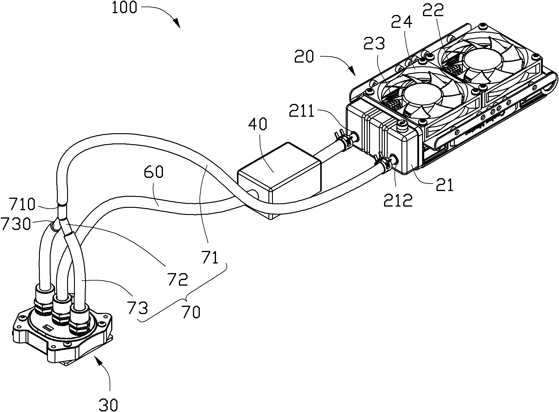
[0017] Please refer to figure 1 , shows a liquid-cooled heat dissipation system 100 in an embodiment of the present invention, the liquid-cooled heat dissipation system 100 includes a heat dissipation element 20, a heat absorption element 30, a drive pump 40, the heat absorption element 30 and the heat dissipation element 20 is connected to a water inlet pipe 60 and a water outlet pipe 70.

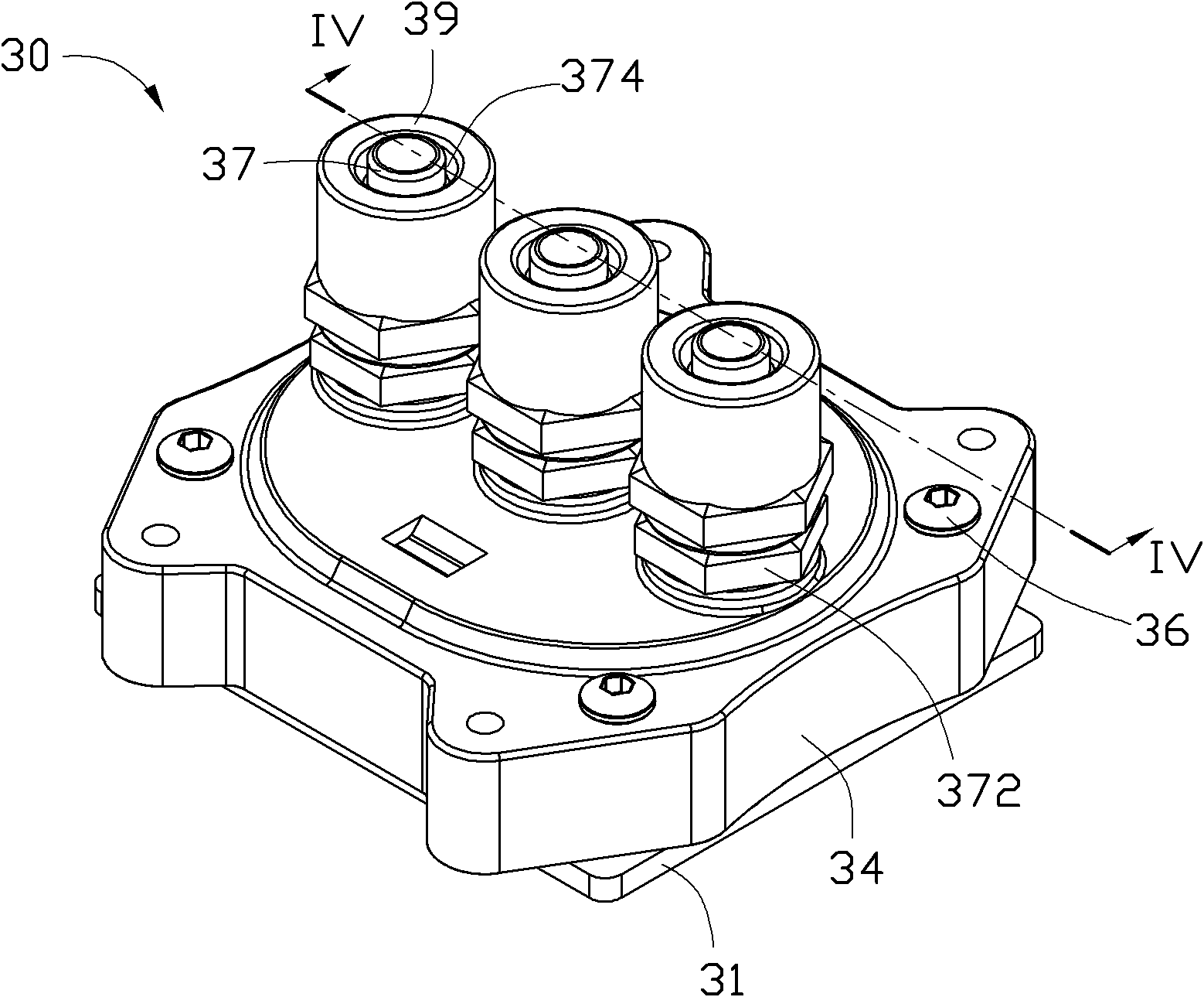
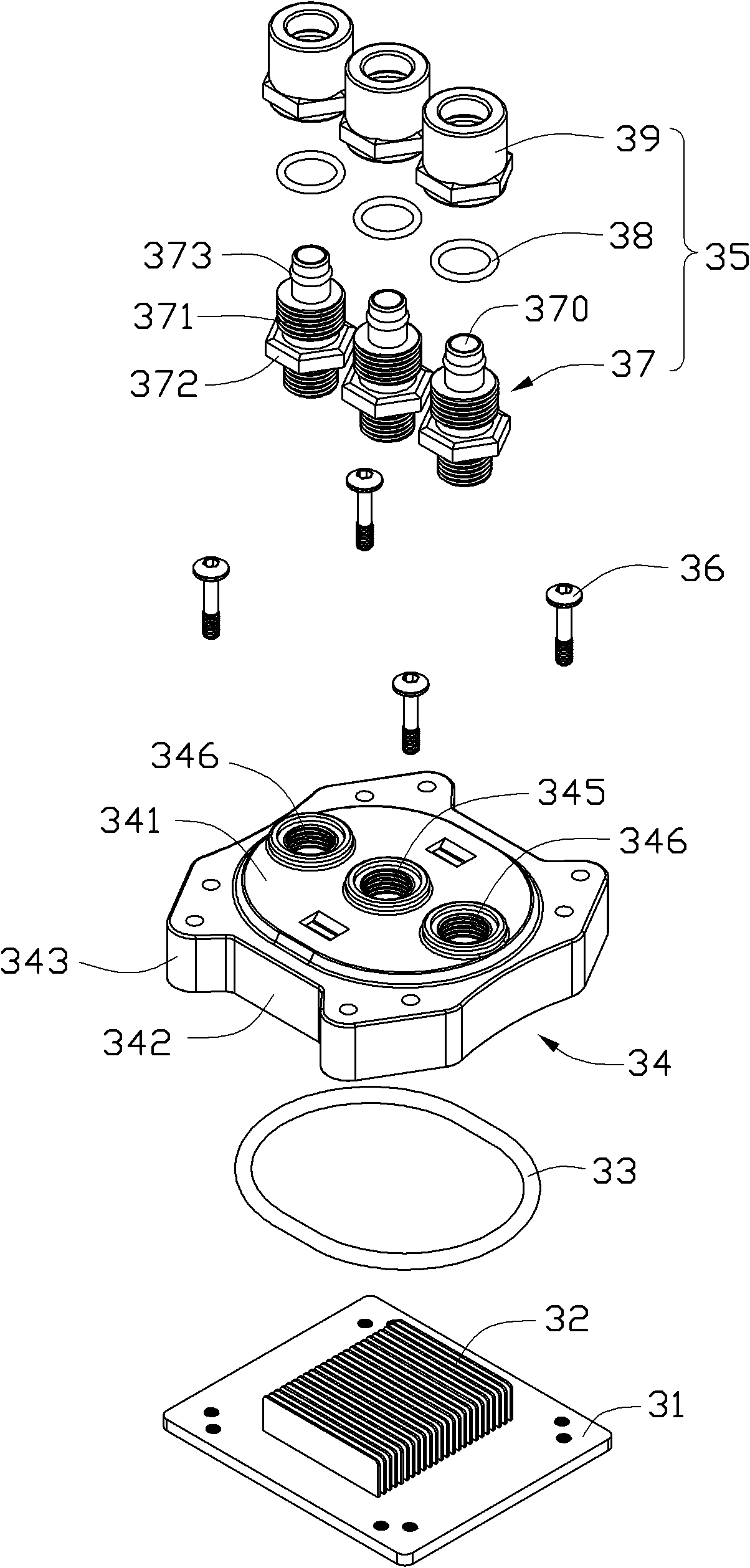
[0018] The heat absorbing element 30 and the heating electronic element 80 ( Figure 4 ), such as the CPU is in close contact, so as to absorb the heat generated by the electronic components 80 in time. Please also see figure 2 and image 3 , the heat absorbing element 30 includes a bottom plate 31 , a radiator 32 , a sealing ring 33 , a cover 34 and three connecting pieces 35 .

[0019] The bottom plate 31 is usually made of a material with better thermal conductivity, such as copper. The cover 34 includes a circular top wall 341 , a side wall 342 extending downward from a periphery...


PUM


Abstract

A liquid-cooled heat dissipation system is disclosed, which comprises a heat absorption component, a drive pump, a heat dissipation component, as well as a water inlet tube and a water outlet tube for connecting the heat absorption component, the drive pump and the heat dissipation component, wherein a sealed chamber for holding a cooling liquid is disposed in the heat absorption component; a heating area attached with an electronic component is formed in the centre of the bottom of the heat absorption component; and a water inlet connected with the water inlet tube and facing the heating area, and a plurality of water outlets connected with the water outlet tube and located around the water inlet are disposed on the top of the heat absorption component.

Description

technical field [0001] The invention relates to a liquid-cooled heat dissipation system, in particular to a liquid-cooled heat dissipation system for cooling electronic components. Background technique [0002] The principle of the liquid-cooled heat dissipation system is to use the circulating flow of liquid to transfer the heat generated by electronic components, such as the central processing unit, to the heat dissipation element, and then dissipate the heat. [0003] Generally, the liquid cooling heat dissipation system includes a driving pump, a heat absorbing element for absorbing heat generated by electronic components, a heat dissipation element, a water inlet pipe and a water outlet pipe. The heat absorbing element is respectively provided with a water inlet connected with the water inlet pipe and a water outlet connected with the water outlet pipe. The water inlet pipe and the water outlet pipe are sequentially connected to the driving pump, the heat absorbing ele...

Claims


Application Information

Patent Timeline
Patent Type & Authority Applications(China)
IPC IPC(8): H01L23/473G06F1/20H05K7/20
CPCH01L23/473G06F2200/201G06F1/20H01L2924/0002H01L2924/00
Inventor 汤贤袖
Owner WARECONN TECH SERVICE (TIANJIN) CO LTD
Learn More