Exhaust gas after treatment system with temperature control

A technology of exhaust aftertreatment and emission control system, which is applied in exhaust treatment, exhaust device, air quality improvement, etc., and can solve problems such as SCR failure

Inactive Publication Date: 2012-05-09
VOLVO TRUCK CORP
View PDF6 Cites 2 Cited by
  • Summary
  • Abstract
  • Description
  • Claims
  • Application Information

AI Technical Summary

Problems solved by technology

If the temperature is too high, the SCR may fail

Method used


Image

  • Exhaust gas after treatment system with temperature control
  • Exhaust gas after treatment system with temperature control
  • Exhaust gas after treatment system with temperature control

Examples


Embodiment Construction

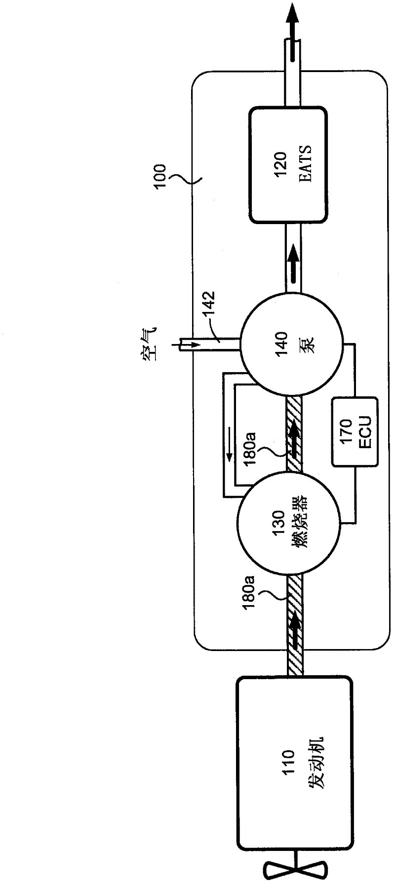
[0024] figure 1 is a general schematic diagram of an emission control system 100 configured to receive exhaust gas from a combustion engine 110 according to one embodiment of the present aspect. Emission control system 100 includes EATS 120 configured to operatively clean exhaust gas received from engine 110 . The emission control system 100 is provided with: a burner unit 130 configured to operably heat the received exhaust gas to a predetermined temperature prior to providing the exhaust gas to the EATS 120; and a pump unit 140 , the pump unit 140 is configured to operatively supply the burner unit 130 with air to be used by the burner unit 130 during heating in the burner unit 130 . Typically, the pump unit 140 is configured to be operably driven by the exhaust gas. The burner unit 130 is arranged upstream of the pump unit 140 so that exhaust gas from the burner unit 130 is operatively provided to the pump unit 140 to drive the pump unit 140 .

[0025] Using a separate b...


PUM


Abstract

Disclosed herein is a vehicle emission control system (300) configured to operatively receive exhaust gas from a combustion engine (110) and comprising an EATS (120) configured to operatively clean the received exhaust gas, a burner unit (130) configured to operatively heat the received exhaust gas to a predetermined temperature before the exhaust gas is provided to the exhaust gas after treatment system (120), and a pump unit (140) configured to operatively provide the burner unit (130) with air to be used by the burner unit (130) in a heating process. The pump unit (140) is configured to be operatively propelled by exhaust gas, and the burner unit (130) is arranged upstream the pump unit (140) such that exhaust gas from the burner unit (130) is operatively provided to the pump unit (140) for propelling the pump unit (140).

Description

technical field [0001] The present invention relates to an arrangement and method for controlling the temperature of exhaust gas from a combustion engine prior to providing the exhaust gas to an exhaust aftertreatment system for cleaning. Background technique [0002] Current emission control regulations for automobiles will typically require the use of exhaust aftertreatment systems (EATS) that include various emission cleaning units. Therefore, most modern automobiles, at least heavy duty vehicles, utilize EATS to clean the exhaust of the vehicle engine. Emission cleaning units of EATS may be, for example, various catalysts capable of converting carbon monoxide (CO), hydrocarbons (HC) and nitrogen oxides (NOx) produced during vehicle engine operation. Other emission cleaning units may be various filters, such as particulate filters designed to remove certain substances or soot, etc., from exhaust gas or the like. [0003] Vehicles equipped with diesel engines offer the b...

Claims


Application Information

Patent Timeline
Patent Type & Authority Applications(China)
IPC IPC(8): F01N3/32F01N3/025
CPCF01N3/32F01N3/2033F01N5/04Y02T10/26F01N3/36Y02T10/16F01N2240/14F01N2270/04Y02T10/12Y02A50/20F01N3/2006
Inventor 让·林德布卢姆马丁·斯乔荷姆拉尔斯·松丁
Owner VOLVO TRUCK CORP
Why Eureka
Try Eureka