
Real-time conversion transmission method and device of parallel-series data stream for cross asynchronous clock domain

A technology of asynchronous clock and transmission method, applied in the direction of parallel/serial conversion, code conversion, electrical components, etc., can solve the problems of increased power consumption, complex circuit structure, unfavorable digital-analog hybrid design, high-speed circuit application, etc.

Active Publication Date: 2012-05-09
ALLWINNER TECH CO LTD
View PDF4 Cites 19 Cited by
  • Summary
  • Abstract
  • Description
  • Claims
  • Application Information

AI Technical Summary

Problems solved by technology

[0005] In the application scenario of real-time and uninterrupted data stream processing, at this time, each parallel clock signal CLKP clock edge brings new parallel data to be processed, so the above method needs to use a large redundant space to cache data on the one hand. , in order to avoid data interruption during asynchronous transmission, that is, the required storage space must be greater than the amount of information in a single data transmission, sometimes even several times more, to ensure its reliability, so the circuit area is larger and the power In addition, the control logic similar to the asynchronous first-in-first-out queue (FIFO) structure needs pointers for reading and writing addresses and arithmetic circuits based on address pointers. The circuit structure is relatively complicated. Under the same conventional process and underlying device library resources , the circuit speed and reliability are obviously inferior to those of the design using this scheme, which is not conducive to some high-speed circuit applications in the digital-analog hybrid design

Method used


Image

  • Real-time conversion transmission method and device of parallel-series data stream for cross asynchronous clock domain
  • Real-time conversion transmission method and device of parallel-series data stream for cross asynchronous clock domain
  • Real-time conversion transmission method and device of parallel-series data stream for cross asynchronous clock domain

Examples


Embodiment 1

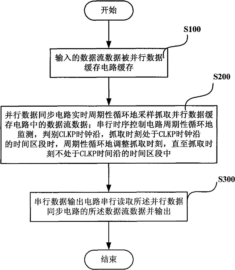
[0102] The real-time conversion and transmission method of the parallel-serial data stream across the asynchronous clock domain in the embodiment of the present invention, such as figure 1 shown, including the following steps:

[0103] Step S100, the input data stream is buffered by a parallel data buffer controlled by a parallel clock signal CLKP synchronized with it;

[0104] Step S200, the parallel data synchronizer 2 synchronized with the serial clock signal CLKS is under the control of the serial clock signal CLKS synchronized with the serial data exporter 4 and the enable control signal CS issued by the serial timing controller 3 , by connecting the first data bus of the parallel data buffer 1 and the parallel data synchronizer 2, the data in the parallel data buffer 1 is periodically sampled and captured in real time and stored in the parallel data synchronizer 2;

[0105] The frequency of the serial clock signal CLKS is N times the frequency of the parallel clock sign...

Embodiment 2

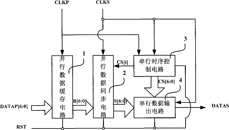
[0129] Such as image 3 As shown, the device for real-time conversion and transmission of parallel-to-serial data streams across asynchronous clock domains according to the embodiment of the present invention includes a parallel data buffer 1, a parallel data synchronizer 2, a serial timing controller 3 and a serial data output device 4;

[0130] The parallel data buffer 1 and the parallel data synchronizer 2 are connected by a first data bus (parallel data bus) identical to the parallel data bit width;

[0131] The parallel data synchronizer 2 is connected to the serial timing controller 3 through a control bus having the same bit width as the parallel data;

[0132] The parallel data synchronizer 2 and the serial data exporter 4 are connected through a second data bus having the same bit width as the serial data;

[0133] As a possible implementation manner, the parallel clock signal CLKP and the serial clock signal CLKS in the embodiment of the present invention may be res...

Embodiment 3

[0219] Taking a device for real-time conversion and transmission of parallel-serial data streams across asynchronous clock domains in an LVDS interface circuit for driving flat panel displays as an example, the device for real-time conversion and transmission of parallel-serial data streams across asynchronous clock domains of the present invention will be further described in detail.

[0220] Such as image 3 As shown, in this embodiment, taking the real-time conversion and transmission device of the parallel-serial data stream across the asynchronous clock domain in the LVDS interface circuit driving the panel display as an example, the real-time conversion of the parallel-serial data stream across the asynchronous clock domain in the embodiment of the present invention However, it should be noted that the device for real-time conversion and transmission of parallel-to-serial data streams across asynchronous clock domains of the present invention is also applicable to other v...


PUM


Abstract

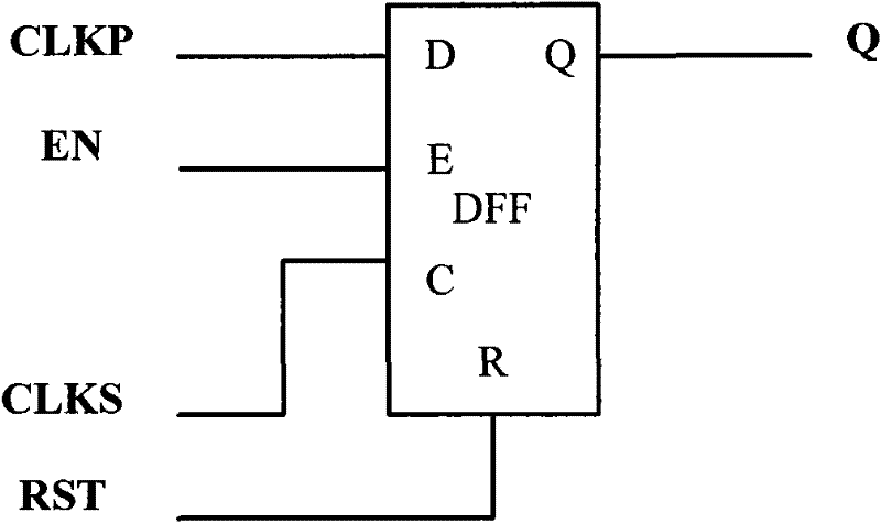
The invention discloses a real-time conversion transmission method and device of parallel-series data stream for cross asynchronous clock domain, comprising a parallel data synchronizer, which is used for capturing the data stream periodically in real time and storing into the parallel data synchronizer under the control of a serial clock CLKS which is synchronous to output device of serial data and an enabling controlling signal CS sent out by serial timing controller which is synchronous to clock CLKP; the serial timing controller, monitoring clock CLKP periodically in the clock domain of clock CLKS, distinguishing indeterminate state of clock CLKP, the indeterminate state being a time domain zone of a data transmission zone; when distinguishing that the capturing moment is in a time zone of the data transmission zone of clock CLKP, the serial timing controller cyclically adjusts capturing moment until the capturing moment is in the time zone of determined state of clock CLKP, the determined state being the time zone besides the data transmission zone; the output device of serial data, reading the data stream of parallel data synchronizer and output serially under the control of the serial timing controller. The invention is characterized by being simple and reliable, good practicability and being in favor of applying in the large scale integrated circuit.

Description

technical field [0001] The invention relates to the technical field of conversion circuits, in particular to a method and device for real-time conversion and transmission of parallel and serial data streams across an asynchronous clock domain. Background technique [0002] Parallel-to-serial conversion circuit is a common data processing circuit that people have studied for a long time, but in some designs people only consider that the input parallel data stream and the output serial data stream are both synchronous clock domains, while in others it is necessary to When solving the problem of parallel-to-serial data conversion in the asynchronous time domain, designers usually use two methods: [0003] Method 1: When data is transferred across asynchronous clock domains, the input data flow can be temporarily stopped, and the next data will be processed after the handshake signal interaction across clock domains is successful. This method is obviously not suitable for those ...

Claims


Application Information

Patent Timeline
Patent Type & Authority Applications(China)
IPC IPC(8): H03M9/00
Inventor 陈传著
Owner ALLWINNER TECH CO LTD
Learn More