Back-twisting wire stranding machine

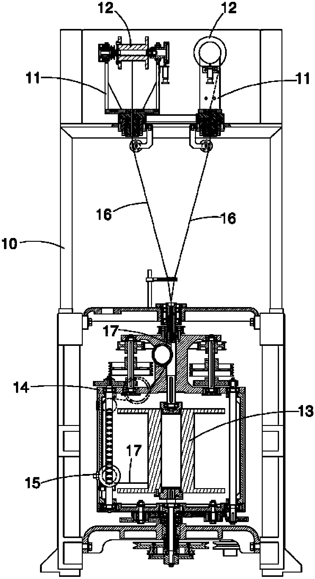
A stranding machine and stranding technology, which is applied to auxiliary devices for rope making, textiles and papermaking, electrical components, etc., can solve the problems that the reel 13 cannot be too large, increase the number of replacements of the reel 13, and affect work efficiency.

Active Publication Date: 2014-04-30
东莞朝隆机械有限公司
View PDF4 Cites 0 Cited by
  • Summary
  • Abstract
  • Description
  • Claims
  • Application Information

AI Technical Summary

Problems solved by technology

However, this known stranding machine still has the problem of complex structure, and the two wire wheel frames 11 are arranged on the top of the machine platform 10, so in order to facilitate the installation of the wire wheel 13, and limited by the power and the size of the machine, the wire wheel 13 that can be installed cannot be too large
Therefore, relatively, the number of times to replace the wire wheel 13 will be increased and the work efficiency will be seriously affected.
[0005] In view of this, the inventor has thought deeply about the lack and inconvenience caused by the imperfect structure and design of the above-mentioned known twisting machine, and actively researched and improved the trial production to develop and design the present invention.

Method used


Image

  • Back-twisting wire stranding machine
  • Back-twisting wire stranding machine
  • Back-twisting wire stranding machine

Examples


Embodiment Construction

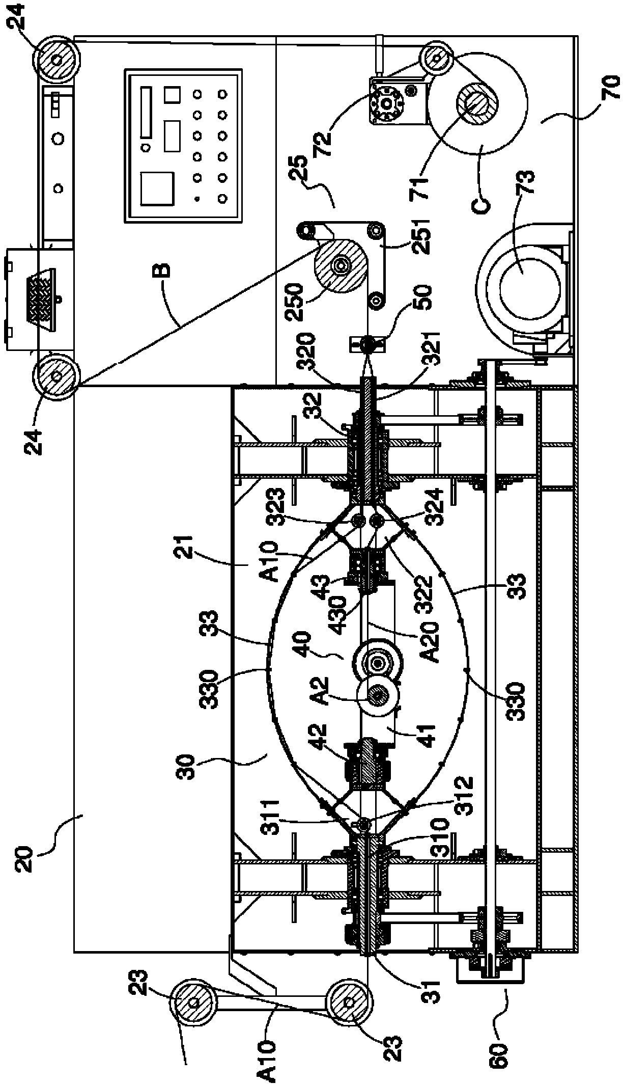
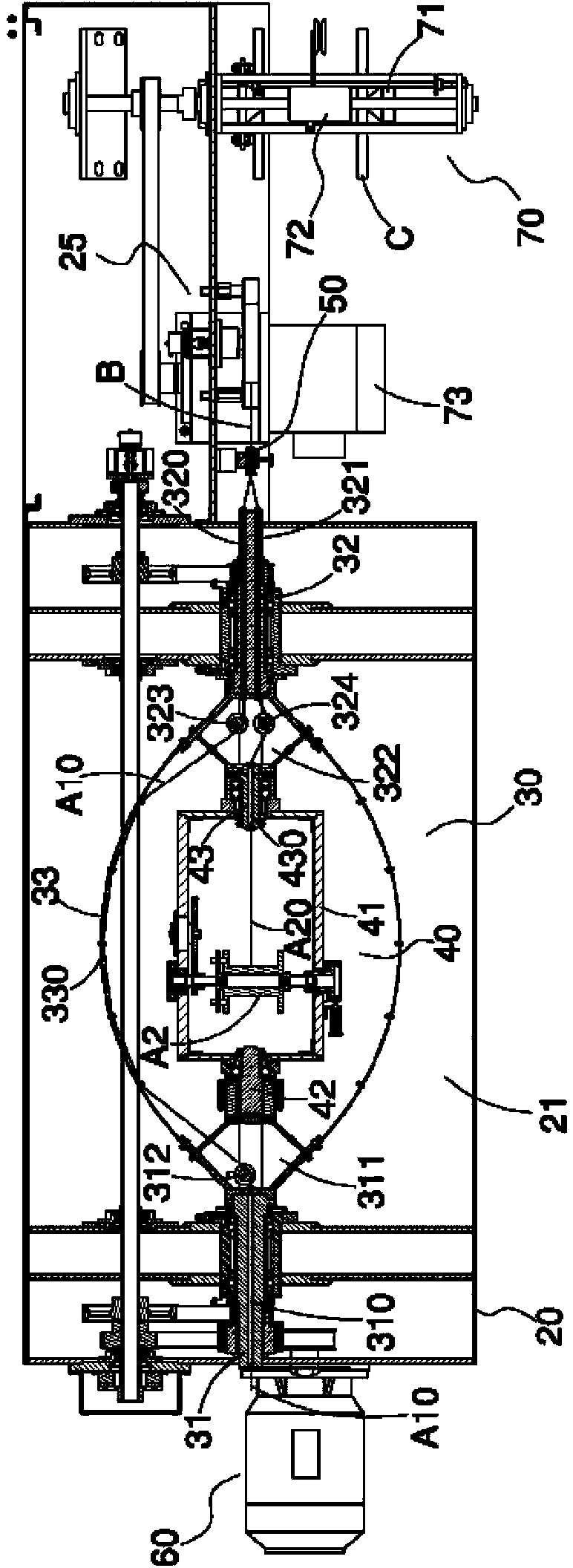
[0051] see Figure 2 to Figure 5 As shown, it is pointed out that the untwisted wire twisting machine of the present invention includes a machine platform 20, a wire twisting device 30, a line wheel frame 40, a twisted wire eye mold 50, a driving device 60, a winding device 70 and a Cover 80. in:

[0052] There is a working chamber 21 in the machine table 20 . The machine platform 20 has a working window 22 connected to the working chamber 21 . There are several freely rotatable leading wire pulleys 23, rear wire pulleys 24 and a pulley set 25 on the machine platform 20. The pulley set 25 can be composed of a pulley 250 and a pulley set 251, and the pulley set 25 can also be double pulleys (not shown in the figure) side by side.

[0053] The wire twisting device 30 includes a first shaft 31 , a second shaft 32 and two bow arms 33 . The first shaft 31 and the second shaft 32 are respectively rotatable and coaxially pass through two opposite side walls of the working chambe...


PUM


Abstract

The invention relates to a back-twisting wire stranding machine, which comprises a board, a wire stranding device, a wire wheel carrier, a wire stranding eye mould and a drive device; the wire stranding device comprises a first shaft, a second shaft and at least one limb, wherein the first and the second shafts are pivoted onto the board, the limb which is provided with a wire guiding module is arranged on the first and the second shafts, and a wire incoming hole is arranged inside the first shaft and is used for a first wire to pass through, and a first wire leading-out hole and a second wire leading-out hole are arranged inside the second shaft; the wire wheel carrier comprises a framework, a first rotating shaft and a second rotating shaft, wherein the framework is provided with a wire wheel, the first and the second rotating shafts are respectively combined with the first and the second shafts in a rotating way, and a shaft hole is arranged in the second rotating shaft; the drive device drives the first and the second shafts to rotate; the first wire passes through the wire guiding module and the first wire leading-out hole and extends into the wire stranding eye mould, a second wire which is wound on the wire wheel passes through the shaft hole and the second wire leading-out hole and extends into the wire stranding eye mould, and the first wire and the second wire are pair stranded in the wire stranding eye mould to form a stranded wire. The back-twisting wire stranding machine has a simple structure and occupies a small space.

Description

technical field [0001] The invention relates to the technical field of a stranding machine, in particular to an untwisting stranding machine which can not only eliminate the torsional stress generated during stranding operation, but also has a simple structure and does not occupy space. Background technique [0002] A commonly known stranding machine, as shown in Taiwan Patent No. 269883, is mainly structured with two shafts that are coaxial and spaced apart by a distance. A turntable is respectively provided on the two shafts, and between the two shafts is a turntable. Two strand racks and one rack. Wherein, the two ends of the two strands are respectively connected to the two turntables, so that the two strands can rotate synchronously with the two rotating shafts. The frame is pivoted on the two shaft tubes for setting a spool to rotate thereon, and a wire arranging device is arranged on the frame. In this way, the two wires are passed through one side of the rotating ...

Claims


Application Information

Patent Timeline
Patent Type & Authority Patents(China)
IPC IPC(8): H01B13/02D07B7/16
Inventor 李东兴
Owner 东莞朝隆机械有限公司
Why Eureka
Try Eureka