
Short-time slowly-varying high-current measuring device based on (printed circuit board) PCB type Rogowski coil

A technology of Rogowski coil and measuring device, which is applied in the direction of measuring device, measuring electrical variables, and voltage/current isolation, etc., to achieve the effect of light structure, small size, and reduction of measurement errors

Active Publication Date: 2012-05-09
NAVAL UNIV OF ENG PLA
View PDF4 Cites 31 Cited by
  • Summary
  • Abstract
  • Description
  • Claims
  • Application Information

AI Technical Summary

Problems solved by technology

[0004] The purpose of the present invention is to overcome the deficiencies of the above-mentioned prior art and provide a method for measuring short-time aperiodic slow-changing large currents in complex electromagnetic environments.

Method used


Image

  • Short-time slowly-varying high-current measuring device based on (printed circuit board) PCB type Rogowski coil
  • Short-time slowly-varying high-current measuring device based on (printed circuit board) PCB type Rogowski coil
  • Short-time slowly-varying high-current measuring device based on (printed circuit board) PCB type Rogowski coil

Examples


Embodiment Construction

[0026] The present invention will be further described below in conjunction with the accompanying drawings and specific embodiments.

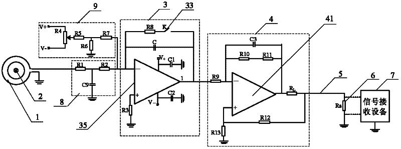
[0027] Such as figure 1 As shown, the short-time slowly changing large current measuring device based on PCB Rogowski coils includes: PCB Rogowski coil 1 , integrating circuit 3 , VI conversion circuit 4 , sampling resistor 6 and signal receiving device 7 . The output end of the PCB type Rogowski coil 1 is connected to the input end of the integral circuit 3, the output end of the integral circuit 3 is connected to the input end of the VI conversion circuit 4, and the output end of the VI conversion circuit 4 is connected to the The sampling resistor 6 is connected, and the signal receiving device 7 is connected to both ends of the sampling resistor.

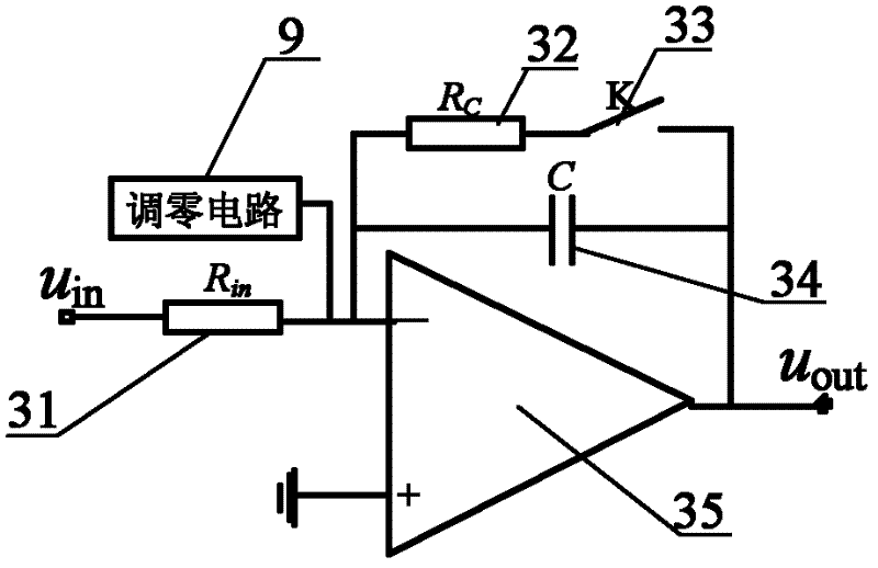
[0028] Such as figure 2 As shown, the integral circuit 3 without inertia link comprises: a zeroing circuit 30, an integrating resistor 31, an operational amplifier 35, an integrating capacitor...


PUM


Abstract

The invention discloses a short-time slowly-varying high-current measuring device based on a (printed circuit board) PCB type Rogowski coil, and the short-time slowly-varying high-current measuring device comprises the PCB type Rogowski coil, a sampling resistor and signal receiving equipment, wherein an inertialess link integrating circuit and a variable interval (VI) switching circuit are additionally and successively arranged between the PCB type Rogowski coil and the sampling resistor; and the PCB type Rogowski coil is a PCB type Rogowski coil which is provided with symmetrically arranged wires on two faces and is provided with return wires. The short time slowly-varying high-current measuring device has the advantages that direct currents or low frequency high currents can be detected, the measuring bandwidth of the short time slowly-varying high-current measuring device can reach up to DC swung dash 200kHz, and the deficiencies of a conventional current sensor on the aspect of measurement of the direct currents or the low frequency high currents are eliminated; and since the PCB type Rogowski coil which is provided with the symmetrically arranged wires and is provided with the return wires is adopted by the short time slowly-varying high-current measuring device as a sensing head, complex electromagnetic interferences in a high-current system can be effectively eliminated, and a full-analog signal transmission manner is adopted by the device, so measurement errors can be effectively reduced.

Description

technical field [0001] The invention relates to a current measuring device, in particular to a short-time slowly changing large current measuring device based on a PCB-type Rogowski coil, which is used for measuring a short-time non-periodic slowly changing large current in a complex electromagnetic environment. Background technique [0002] The current linear induction motor adopts the short-term power supply method of segmental work, such as: the linear induction motor used as a propulsion machine for high-power density systems such as maglev trains and electromagnetic launches, and its operating current has a large amplitude (up to tens of kA). , The frequency is low (DC ~ 80Hz), the duration is short (usually a few seconds to more than ten seconds) and the current is a non-periodic signal. Due to the large current amplitude, there is a defect of saturation distortion when using a current sensor with an iron core such as a Hall coil; although the working duration is short...

Claims


Application Information

Patent Timeline
IPC IPC(8): G01R19/00G01R15/18
Inventor 陶涛赵治华李文禄马伟明腾腾唐健潘启军张磊张向明胡安琪吴文力
Owner NAVAL UNIV OF ENG PLA
Learn More